FRONT SHOCK ABSORBER INSTALLATION

Tech Tips
-
Use the same procedures for the RH side and LH side.
-
The procedures listed below are for the LH side.
-
A bolt without a torque specification is shown in the standard bolt chart Click here.
-
TEMPORARILY INSTALL FRONT SHOCK ABSORBER WITH COIL SPRING
-
Temporarily install the upper side of the shock absorber to the chassis frame with the 4 nuts.
-
Temporarily install the lower side of the shock absorber to the lower suspension arm with the bolt and nut.
-
-
CONNECT NO. 2 SUSPENSION CONTROL PRESSURE HOSE (w/ Active Height Control)
-
Apply MP grease to the O-ring and back -up ring of the suspension control pressure hose.
-
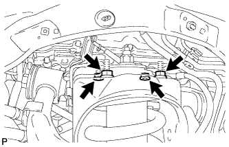
Connect the suspension control pressure hose to the shock absorber with the 2 bolts.
- Torque:
- 18 N*m { 184 kgf*cm, 13 ft.*lbf }
Note
Do not allow any foreign matter such as dirt and dust to enter the suspension control pressure hose from the connecting point.
-
-
BLEED AIR FROM SUSPENSION FLUID (w/ Active Height Control)
-
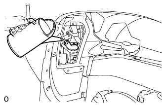
With the engine stopped, fill the reservoir tank with fluid.
Note
When the engine starts, the pump operates and fluid is supplied to each cylinder from the reservoir tank. Therefore, add the necessary amount of fluid so that the reservoir tank does not become empty.
Tech Tips
At this point, the vehicle height is low because the pressure of the cylinders is low.
-
With the vehicle on a level surface, start the engine and set the vehicle height to NORMAL with the suspension control switch.
-
When the vehicle height becomes NORMAL and the pump stops, stop the engine.
-
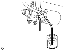
Connect a hose to the bleeder plug of the front left side or right side control valve, then loosen the bleeder plug.
CAUTION:
Be careful when loosening the control valve bleeder plug because the front vehicle height drops rapidly.
-
After the fluid containing air stops coming out, retighten the bleeder plug.
- Torque:
- 8.3 N*m { 85 kgf*cm, 73 in.*lbf }
Tech Tips
If the procedures are performed for the first time on the left side, perform the procedures on the right side for the second time.
-
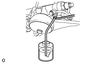
Connect a hose to the bleeder plug of the rear left side or right side control valve, then loosen the bleeder plug.
CAUTION:
Be careful when loosening the control valve bleeder plug because the rear vehicle height drops rapidly.
-
After the fluid containing air stops coming out, retighten the bleeder plug.
- Torque:
- 8.3 N*m { 85 kgf*cm, 73 in.*lbf }
Tech Tips
If the procedures are performed for the first time on the left side, perform the procedures on the right side for the second time.
-
Repeat the previous 4 procedures until the fluid containing air stop coming out.
-
-
CHECK FLUID LEVEL IN RESERVOIR (w/ Active Height Control)
-
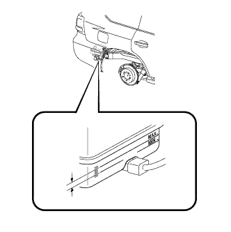
With the vehicle empty, after setting the vehicle height to NORMAL from LO, check the indicator to make sure the vehicle height is NORMAL and check that the fluid level in the reservoir tank is within the specified range (MAX, MIN).
Tech Tips
After changing the vehicle height from LO to NORMAL, do not stop the engine for 25 seconds because the pressure control for the main accumulator is operating. After that, check the fluid level.
-
-
INSPECT FOR SUSPENSION FLUID LEAK (w/ Active Height Control)
-
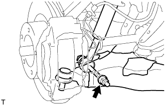
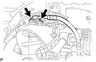
Check that the union nuts shown in the illustration are tightened to the specified torque.
- Torque:
- without union nut wrench
- 15 N*m { 155 kgf*cm, 11 ft.*lbf }
- with union nut wrench
- 14 N*m { 143 kgf*cm, 10 ft.*lbf }
Tech Tips
-
Use a torque wrench with a fulcrum length of 300 mm (11.8 in.).
-
The torque value for use with a union nut wrench is effective when the union nut wrench is parallel to the torque wrench.
-
Check for fluid leakage from the parts and connections.
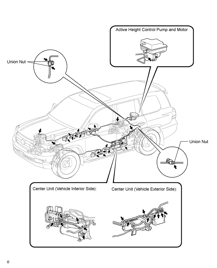
Tech Tips
For union nuts and union bolts not shown in the illustration, refer to the installation procedures for each title.
-
-
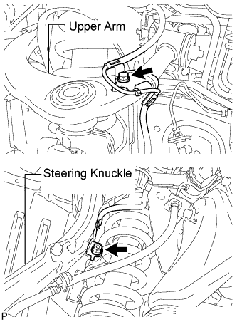
CONNECT STEERING KNUCKLE LH
-
Connect the steering knuckle to the suspension upper arm.
-
Install the nut and a new cotter pin.
- Torque:
- 110 N*m { 1122 kgf*cm, 81 ft.*lbf }
Note
If the holes for the cotter pin are not aligned, tighten the nut further up to 60°.
-
-
CONNECT SKID CONTROL SENSOR WIRE
-
Connect the sensor wire to the steering knuckle and upper arm with the bolt and nut.
- Torque:
- 13 N*m { 133 kgf*cm, 9.6 ft.*lbf }
-
-
INSTALL FRONT FENDER APRON TRIM PACKING D (w/ Active Height Control)
-
Install the apron trim packing with the 4 clips.
-
-
INSTALL FRONT FENDER APRON TRIM PACKING B (w/ Active Height Control)
-
Install the apron trim packing with the 4 clips.
-
-
TEMPORARILY INSTALL FRONT STABILIZER LINK ASSEMBLY RH
-
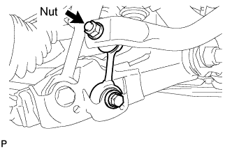
Temporarily install the stabilizer link with the bolt.
-
Temporarily install the stabilizer link with the nut.
-
Tighten the nut.
- Torque:
- 128 N*m { 1305 kgf*cm, 94 ft.*lbf }
-
-
TEMPORARILY INSTALL FRONT STABILIZER LINK ASSEMBLY LH (w/ KDSS)
-
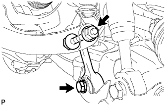
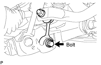
Temporarily install the stabilizer link to the lower arm with the bolt.
-
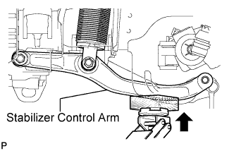
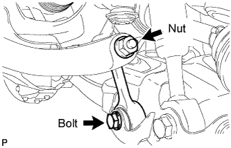
Temporarily install the stabilizer link to the stabilizer control arm with the bolt and nut.
Tech Tips
If the front stabilizer control cylinder extends and it is difficult to temporarily install the stabilizer link to the stabilizer control arm, raise the stabilizer control arm with a jack and temporarily install the stabilizer link.
-
-
TEMPORARILY INSTALL FRONT STABILIZER LINK ASSEMBLY LH (w/o KDSS)
-
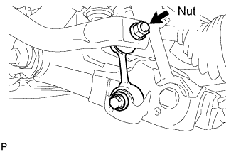
Temporarily install the stabilizer link with the nut and bolt.
-
Tighten the nut.
- Torque:
- 128 N*m { 1305 kgf*cm, ft.*lbf }
-
-
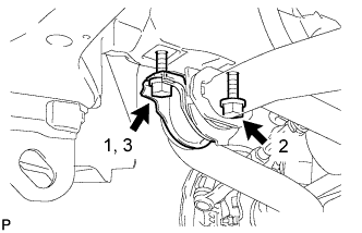
TIGHTEN FRONT NO. 1 STABILIZER BRACKET LH
-
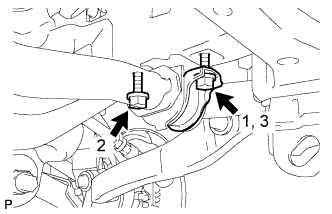
Tighten the 2 bolts of the front stabilizer brackets.
- Torque:
- 87 N*m { 887 kgf*cm, 64 ft.*lbf }
Note
Tighten the bolts in 3 steps, in the order shown in the illustration.
-
-
TIGHTEN FRONT NO. 1 STABILIZER BRACKET RH
-
Tighten the 2 bolts of the front stabilizer brackets.
- Torque:
- 87 N*m { 887 kgf*cm, 64 ft.*lbf }
Note
Tighten the bolts in 3 steps, in the order shown in the illustration.
-
-
INSTALL NO. 1 ENGINE UNDER COVER SUB-ASSEMBLY
-
Install the No. 1 engine under cover sub-assembly with the 10 bolts.
- Torque:
- 29 N*m { 296 kgf*cm, 21 ft.*lbf }
-
-
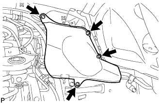
INSTALL FRONT FENDER SPLASH SHIELD SUB-ASSEMBLY LH
-
Push in the clip to install the front fender splash shield sub-assembly LH.
-
Install the 3 bolts and screw.
-
-
INSTALL FRONT FENDER SPLASH SHIELD SUB-ASSEMBLY RH
-
Push in the clip to install the front fender splash shield sub-assembly RH.
-
Install the 3 bolts and 2 screws.
-
-
STABILIZE SUSPENSION
-
Install the front wheels.
- Torque:
- for aluminum wheel
- 131 N*m { 1336 kgf*cm, 97 ft.*lbf }
- for steel wheel
- 209 N*m { 2131 kgf*cm, 154 ft.*lbf }
-
Lower the vehicle.
-
Press down on the vehicle several times to stabilize the suspension.
-
-
TIGHTEN FRONT SHOCK ABSORBER WITH COIL SPRING
-
Tighten the nut.
- Torque:
- 180 N*m { 1835 kgf*cm, 133 ft.*lbf }
Note
Perform this procedure with all 4 wheels on the ground.
-
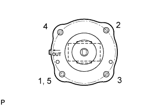
Tighten the 4 upper nuts in diametrically opposite pairs.
- Torque:
- 45 N*m { 459 kgf*cm, 33 ft.*lbf }
-
Check that the first nut that was tightened is at the torque specification.
-
-
TIGHTEN FRONT STABILIZER LINK ASSEMBLY LH (w/ KDSS)
-
Tighten the bolt.
- Torque:
- 135 N*m { 1377 kgf*cm, 100 ft.*lbf }
-
Tighten the nut.
- Torque:
- 140 N*m { 1428 kgf*cm, 103 ft.*lbf }
Note
Perform this procedure with all 4 wheels on the ground.
-
-
TIGHTEN FRONT STABILIZER LINK ASSEMBLY LH (w/o KDSS)
-
Tighten the bolt.
- Torque:
- 135 N*m { 1377 kgf*cm, 100 ft.*lbf }
Note
Perform this procedure with all 4 wheels on the ground.
-
-
TIGHTEN FRONT STABILIZER LINK ASSEMBLY RH
-
Tighten the bolt.
- Torque:
- 135 N*m { 1377 kgf*cm, 100 ft.*lbf }
Note
Perform this procedure with all 4 wheels on the ground.
-
-
PERFORM VEHICLE HEIGHT OFFSET CALIBRATION (w/ Active Height Control)
-
Perform the vehicle height offset calibration Click here.
-
-
MEASURE VEHICLE HEIGHT (w/ KDSS)
Note
-
Perform the inspection on a level surface.
-
Ensure that the wheels are on the ground and facing straight ahead.
-
Perform the inspection with the vehicle load completely on the suspension.
Tech Tips
-
Perform this step with the fuel tank full.
-
If there are any parts installed to the vehicle which place any unbalanced load on the left or right side of the vehicle, remove them.
-
Set the tire pressure to the specified value(s) Click here.
-
Bounce the vehicle to stabilize the suspension.
-
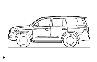
Measure the distance from the ground to the top of the bumper and calculate the difference in the vehicle height between left and right. Perform this procedure for both the front and rear wheels.
Height difference of left and right sides 15 mm (0.591 in.) or less Tech Tips
If not as specified, perform the vehicle tilt calibration.
-
-
CLOSE STABILIZER CONTROL WITH ACCUMULATOR HOUSING SHUTTER VALVE (w/ KDSS)
Note
-
Perform the inspection on a level surface.
-
Ensure that the wheels are on the ground and facing straight ahead.
-
Perform the inspection with the vehicle load completely on the suspension.
Tech Tips
-
Perform this step with the fuel tank full.
-
If there are any parts installed to the vehicle which place any unbalanced load on the left or right side of the vehicle, remove them.
-
Using a 5 mm hexagon socket wrench, tighten the lower and upper chamber shutter valves of the stabilizer control with accumulator housing.
- Torque:
- 14 N*m { 143 kgf*cm, 10 ft.*lbf }
-
-
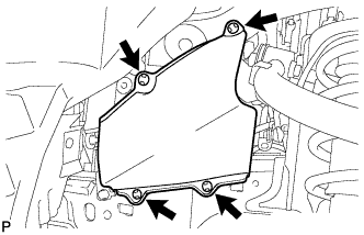
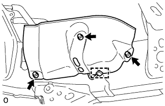
INSTALL STABILIZER CONTROL VALVE PROTECTOR (w/ KDSS)
-
Install the valve protector with the 3 bolts.
- Torque:
- 18 N*m { 184 kgf*cm, 13 ft.*lbf }
-
Attach the clamp, and connect the connector to the valve protector.
-