SUSPENSION CONTROL CYLINDER INSTALLATION

-
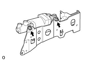
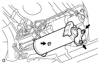
INSTALL CENTER SUSPENSION CONTROL CYLINDER SUB-ASSEMBLY
-
Install the cylinder to the bracket with the 2 nuts.
- Torque:
- 31 N*m { 316 kgf*cm, 23 ft.*lbf }
-
-
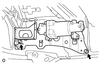
INSTALL HEIGHT CONTROL BRACKET WITH CYLINDER ASSEMBLY
-
Install the bracket with cylinder with the 2 bolts.
- Torque:
- 31 N*m { 316 kgf*cm, 23 ft.*lbf }
-
-
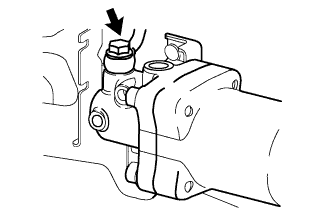
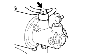
CONNECT NO. 3 HEIGHT CONTROL TUBE LH
-
Install a new gasket to the No. 3 height control tube, and then connect the height control tube to the control cylinder with the union bolt.
- Torque:
- 50 N*m { 510 kgf*cm, 37 ft.*lbf }
-
-
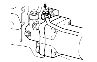
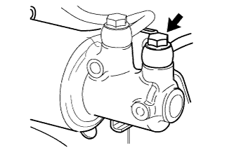
CONNECT NO. 4 HEIGHT CONTROL TUBE
-
Install a new gasket to the No. 4 height control tube, and then connect the height control tube to the control cylinder with the union bolt.
- Torque:
- 50 N*m { 510 kgf*cm, 37 ft.*lbf }
-
-
CONNECT NO. 4 HEIGHT CONTROL TUBE LH
-
Install a new gasket to the No. 4 height control tube, and then connect the height control tube to the control cylinder with the union bolt.
- Torque:
- 50 N*m { 510 kgf*cm, 37 ft.*lbf }
-
-
CONNECT NO. 3 HEIGHT CONTROL TUBE
-
Install a new gasket to the No. 3 height control tube, and then connect the height control tube to the control cylinder with the union bolt.
- Torque:
- 50 N*m { 510 kgf*cm, 37 ft.*lbf }
-
-
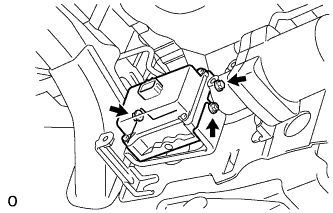
INSTALL NO. 1 HEIGHT CONTROL VALVE ASSEMBLY
-
Install the 3 bolt cushions and 3 bolt holders to the control valve.
-
Install the control valve with the 3 nuts.
- Torque:
- 5.5 N*m { 56 kgf*cm, 49 in.*lbf }
-
-
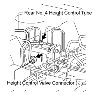
CONNECT REAR NO. 4 HEIGHT CONTROL TUBE
-
Install a new gasket to the control tube, and connect the control tube with the union bolt.
- Torque:
- 25 N*m { 255 kgf*cm, 18 ft.*lbf }
-
Connect the height control valve connector.
-
-
INSTALL NO. 5 HEIGHT CONTROL TUBE
-
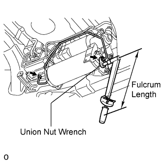
Using a union nut wrench, install the No. 5 control tube to the control valve and center cylinder.
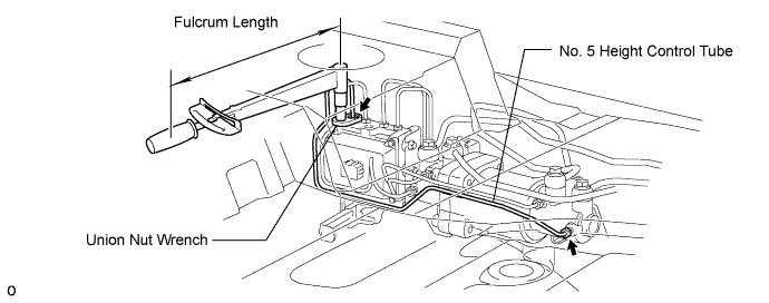
- Torque:
- without union nut wrench
- 15 N*m { 155 kgf*cm, 11 ft.*lbf }
- with union nut wrench
- 14 N*m { 143 kgf*cm, 10 ft.*lbf }
Tech Tips
-
Use a torque wrench with a fulcrum length of 300 mm (11.8 in.).
-
The torque value for use with a union nut wrench is effective when the union nut wrench is parallel to the torque wrench.
-
-
INSTALL NO. 5 HEIGHT CONTROL TUBE LH
-
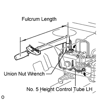
Using a union nut wrench, install the No. 5 control tube to the control valve and center cylinder.
- Torque:
- without union nut wrench
- 15 N*m { 155 kgf*cm, 11 ft.*lbf }
- with union nut wrench
- 14 N*m { 143 kgf*cm, 10 ft.*lbf }
Tech Tips
-
Use a torque wrench with a fulcrum length of 300 mm (11.8 in.).
-
The torque value for use with a union nut wrench is effective when the union nut wrench is parallel to the torque wrench.
-
-
INSTALL NO. 6 HEIGHT CONTROL TUBE LH
-
Using a union nut wrench, install the No. 6 control tube to the control valve and center cylinder.
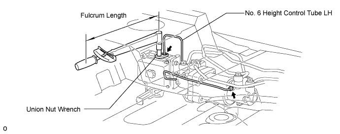
- Torque:
- without union nut wrench
- 15 N*m { 155 kgf*cm, 11 ft.*lbf }
- with union nut wrench
- 14 N*m { 143 kgf*cm, 10 ft.*lbf }
Tech Tips
-
Use a torque wrench with a fulcrum length of 300 mm (11.8 in.).
-
The torque value for use with a union nut wrench is effective when the union nut wrench is parallel to the torque wrench.
-
-
INSTALL NO. 6 HEIGHT CONTROL TUBE
-
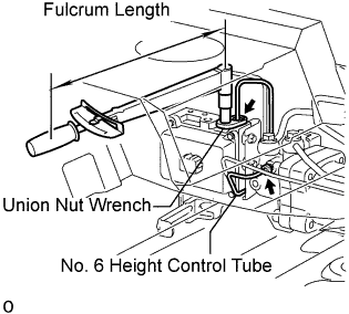
Using a union nut wrench, install the No. 6 control tube to the control valve and center cylinder.
- Torque:
- without union nut wrench
- 15 N*m { 155 kgf*cm, 11 ft.*lbf }
- with union nut wrench
- 14 N*m { 143 kgf*cm, 10 ft.*lbf }
Tech Tips
-
Use a torque wrench with a fulcrum length of 300 mm (11.8 in.).
-
The torque value for use with a union nut wrench is effective when the union nut wrench is parallel to the torque wrench.
-
-
INSTALL CLAMP
-
Install the clamp to the 3 height control tube.
-
-
INSTALL SUSPENSION CONTROL PUMP ACCUMULATOR ASSEMBLY
-
Install the accumulator with the 3 nuts.
- Torque:
- 31 N*m { 316 kgf*cm, 23 ft.*lbf }
-
-
INSTALL NO. 7 HEIGHT CONTROL TUBE
-
Using a union nut wrench, install the No. 7 control tube to the control valve and accumulator.
- Torque:
- without union nut wrench
- 15 N*m { 155 kgf*cm, 11 ft.*lbf }
- with union nut wrench
- 14 N*m { 143 kgf*cm, 10 ft.*lbf }
Tech Tips
-
Use a torque wrench with a fulcrum length of 300 mm (11.8 in.).
-
The torque value for use with a union nut wrench is effective when the union nut wrench is parallel to the torque wrench.
-
-
BLEED AIR FROM SUSPENSION FLUID
-
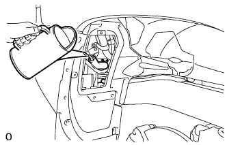
With the engine stopped, fill the reservoir tank with fluid.
Note
When the engine starts, the pump operates and fluid is supplied to each cylinder from the reservoir tank. Therefore, add the necessary amount of fluid so that the reservoir tank does not become empty.
Tech Tips
At this point, the vehicle height is low because the pressure of the cylinders is low.
-
With the vehicle on a level surface, start the engine and set the vehicle height to NORMAL with the suspension control switch.
-
When the vehicle height becomes NORMAL and the pump stops, stop the engine.
-
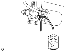
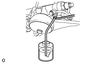
Connect a hose to the bleeder plug of the front left side or right side control valve, then loosen the bleeder plug.
CAUTION:
Be careful when loosening the control valve bleeder plug because the front vehicle height drops rapidly.
-
After the fluid containing air stops coming out, retighten the bleeder plug.
- Torque:
- 8.3 N*m { 85 kgf*cm, 73 in.*lbf }
Tech Tips
If the procedures are performed for the first time on the left side, perform the procedures on the right side for the second time.
-
Connect a hose to the bleeder plug of the rear left side or right side control valve, then loosen the bleeder plug.
CAUTION:
Be careful when loosening the control valve bleeder plug because the rear vehicle height drops rapidly.
-
After the fluid containing air stops coming out, retighten the bleeder plug.
- Torque:
- 8.3 N*m { 85 kgf*cm, 73 in.*lbf }
Tech Tips
If the procedures are performed for the first time on the left side, perform the procedures on the right side for the second time.
-
Repeat the previous 4 procedures until the fluid containing air stop coming out.
-
-
CHECK FLUID LEVEL IN RESERVOIR
-
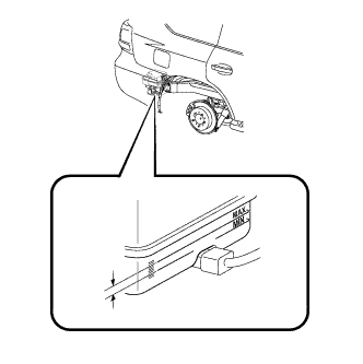
With the vehicle empty, after setting the vehicle height to NORMAL from LO, check the indicator to make sure the vehicle height is NORMAL and check that the fluid level in the reservoir tank is within the specified range (MAX, MIN).
Tech Tips
After changing the vehicle height from LO to NORMAL, do not stop the engine for 25 seconds because the pressure control for the main accumulator is operating. After that, check the fluid level.
-
-
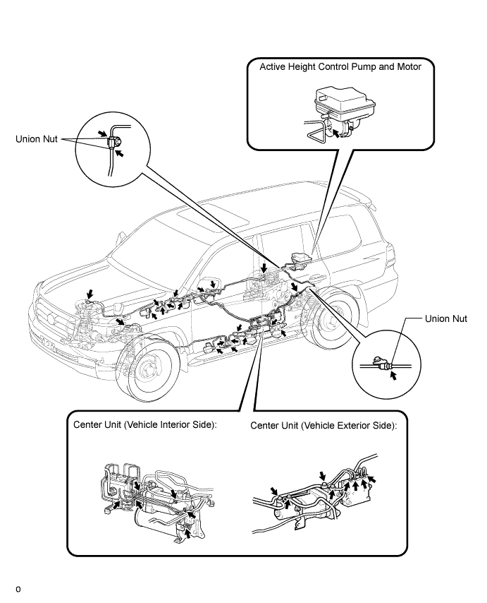
INSPECT FOR SUSPENSION FLUID LEAK
-
Check that the union nuts shown in the illustration are tightened to the specified torque.
- Torque:
- without union nut wrench
- 15 N*m { 155 kgf*cm, 11 ft.*lbf }
- with union nut wrench
- 14 N*m { 143 kgf*cm, 10 ft.*lbf }
Tech Tips
-
Use a torque wrench with a fulcrum length of 300 mm (11.8 in.).
-
The torque value for use with a union nut wrench is effective when the union nut wrench is parallel to the torque wrench.
-
Check for fluid leakage from the parts and connections.
Tech Tips
For union nuts and union bolts not shown in the illustration, refer to the installation procedures for each title.
-
-
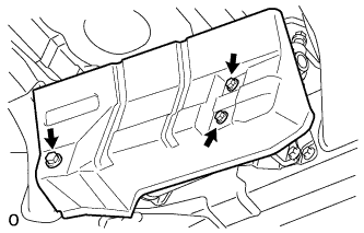
INSTALL HEIGHT CONTROL UNIT INSULATOR
-
Install the insulator to the height control unit with the 3 bolts.
- Torque:
- 31 N*m { 316 kgf*cm, 23 ft.*lbf }
-
-
INSTALL CENTER EXHAUST PIPE ASSEMBLY
-
for 1GR-FE:
Install the center exhaust pipe Click here.
-
for 1UR-FE:
Install the center exhaust pipe Click here.
-
for 3UR-FE:
Install the center exhaust pipe Click here.
-
for 1VD-FTV:
Install the center exhaust pipe Click here.
-
-
INSTALL TAILPIPE ASSEMBLY
-
for 1GR-FE:
Install the tailpipe Click here.
-
for 1UR-FE:
Install the tailpipe Click here.
-
for 3UR-FE:
Install the tailpipe Click here.
-
for 1VD-FTV:
Install the tailpipe Click here.
-
-
INSPECT FOR EXHAUST GAS LEAK
-
If gas is leaking, tighten the areas necessary to stop the leak. Replace damaged parts as necessary.
-