REAR DIFFERENTIAL CARRIER ASSEMBLY (w/ Differential Lock) REASSEMBLY

-
INSPECT DIFFERENTIAL SIDE GEAR BACKLASH
-
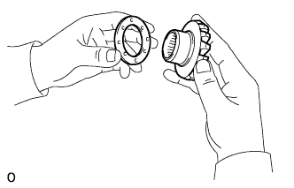
Install the 2 thrust washers to the 2 side gears.
-
Install the 4 thrust washers to the 4 pinion gears.
-
Install the 2 side gears into the differential case.
-
Install the holder into the differential case.
-
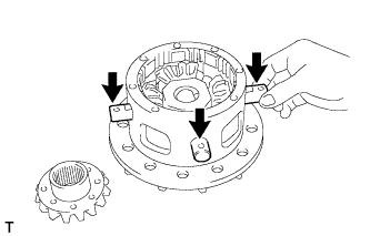
Install the 4 pinion gears.
-
Align the holes of the differential case and pinion shaft, and install the 3 pinion shafts.
-
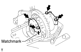
Align the matchmarks and install the differential cover to the differential case.
-
Temporarily install the 5 bolts and 3 pinion shaft pins.
-
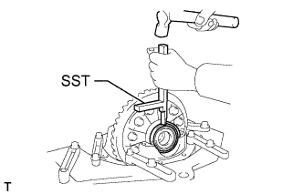
Using a T10 "TORX" socket, tighten the 5 bolts and 3 pinion shaft pins.
- Torque:
- 58 N*m { 590 kgf*cm, 43 ft.*lbf }
-
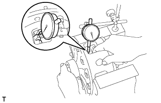
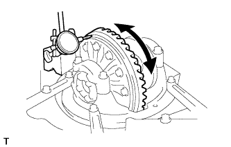
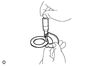
Using a dial indicator, while holding the side gear, measure the backlash.
Standard backlash 0.02 to 0.15 (0.000787 to 0.00591 in.) If the backlash is not within the specification, replace the side gear thrust washers with washers of a different thickness.
Tech Tips
-
Make sure the washers on both sides are the same size.
-
Measure at all 4 pinion gear locations.
-
Apply hypoid gear oil to each sliding surface and rotating part.
Standard Thrust Washer Thickness Specified Condition Specified Condition 1.53 to 1.57 mm (0.0602 to 0.0618 in.) 1.83 to 1.87 mm (0.0721 to 0.0737 in.) 1.58 to 1.62 mm (0.0622 to 0.0638 in.) 1.88 to 1.92 mm (0.0740 to 0.0756 in.) 1.63 to 1.67 mm (0.0641 to 0.0657 in.) 1.93 to 1.97 mm (0.0760 to 0.0776 in.) 1.68 to 1.72 mm (0.0661 to 0.0677 in.) 1.98 to 2.02 mm (0.0780 to 0.0795 in.) 1.73 to 1.77 mm (0.0681 to 0.0697 in.) 2.03 to 2.07 mm (0.0799 to 0.0815 in.) 1.78 to 1.82 mm (0.0701 to 0.0717 in.) 2.08 to 2.12 mm (0.0820 to 0.0835 in.) -
-
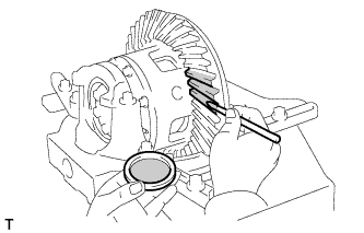
After measuring the backlash, remove the 5 set bolts and 3 pinion shaft pins.
-
-
ASSEMBLE DIFFERENTIAL CASE
-
Clean the threads of the bolts, pinion shaft pins, case and cover with non-residue solvent.
-
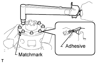
Coat the threads of the bolts and pinion shafts with adhesive.
Adhesive Toyota Genuine Adhesive 1324, Three Bond 1324 or equivalent -
Align the matchmarks of the case and cover.
-
Using a T10 "TORX" socket, install the 5 bolts and 3 pinion shaft pins.
- Torque:
- 58 N*m { 590 kgf*cm, 43 ft.*lbf }
-
-
INSTALL REAR DIFFERENTIAL CASE BEARING
-
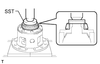
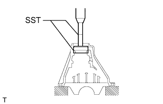
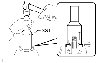
Differential Cover Side:
Using SST and a press, press the side bearing onto the differential cover.
- SST
- 09550-60010
-
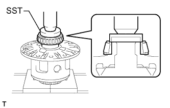
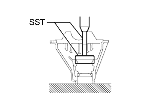
Ring Gear Side:
Using SST and a press, press the side bearing onto the differential case.
- SST
- 09550-60010
-
-
INSTALL DIFFERENTIAL RING GEAR
-
Clean the threads of the bolts and differential case with non-residue solvent.
-
Clean the contact surface of the differential case and ring gear.
-
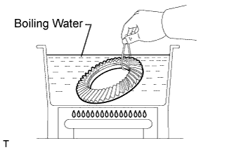
Heat the ring gear to about 100°C (212°F) in boiling water.
-
Carefully take the ring gear out of the boiling water.
-
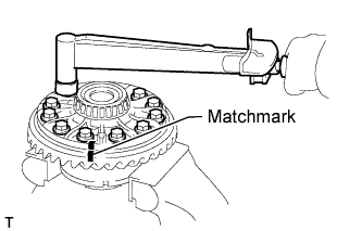
After the moisture on the ring gear has completely evaporated, quickly align the matchmarks on the ring gear and differential case and set the ring gear onto the differential case. Then temporarily install the 12 bolts so that the bolt holes in the ring gear and differential case are aligned.
-
After the ring gear cools down sufficiently, remove the 12 bolts. Then apply thread lock adhesive to the 12 bolts and install them.
Thread lock Toyota Genuine Adhesive 1360K, Three Bond 1360K or equivalent - Torque:
- 137 N*m { 1397 kgf*cm, 101 ft.*lbf }
-
-
INSPECT RUNOUT OF DIFFERENTIAL RING GEAR
-
Place the bearing outer races on their respective bearings.
Tech Tips
Do not interchange the left and right outer races.
-
Install the assembled plate washers to the side bearing.
-
Install the differential case to the differential carrier.
Tech Tips
If it is difficult to install the differential case to the carrier, replace the plate washer with a thinner one.
However, select a plate washer that allows no clearance between it and the carrier.
-
Align the matchmarks on the bearing caps and differential carrier.
-
Install and uniformly tighten the 4 bolts a little at a time.
-
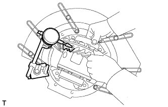
Using a dial indicator, check the ring gear runout.
Maximum runout 0.05 mm (0.00197 in.) If the runout is more than the maximum, replace the ring gear.
-
Remove the differential case.
-
-
INSTALL REAR DRIVE PINION FRONT TAPERED ROLLER BEARING
-
Using SST and a press, press in the front bearing outer race.
- SST
- 09950-60020 ( 09951-00710 )
- 09950-70010 ( 09951-07150 )
-
-
INSTALL REAR DRIVE PINION REAR TAPERED ROLLER BEARING
-
Using SST and a press, press in the rear bearing outer race.
- SST
- 09950-60020 ( 09951-00890 )
- 09950-70010 ( 09951-07150 )
-
-
INSTALL REAR DRIVE PINION REAR TAPERED ROLLER BEARING
-
Install the washer to the drive pinion.
Tech Tips
After installing the washer, check the tooth contact pattern. If necessary, replace the washer with one of a different thickness.
-
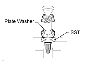
Using SST and a press, press the rear bearing into the drive pinion.
- SST
- 09506-35010
-
-
INSPECT DRIVE PINION PRELOAD
-
Install the drive pinion and front bearing.
Tech Tips
Assemble the spacer and oil seal after adjusting the gear contact pattern.
-
Install the oil slinger.
-
Using SST, install the companion flange.
- SST
- 09950-30012 ( 09951-03010, 09953-03010, 09954-03010, 09955-03030, 09956-03040 )
-
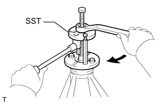
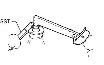
Using SST to hold the flange, adjust the drive pinion preload by tightening the nut.
- SST
- 09330-00021 ( 09330-00030 )
Note
-
Coat the nut and threads of the drive pinion with gear oil.
-
As there is no spacer, tighten the nut a little at a time, being careful not to overtighten it.
-
Using a torque wrench, measure the preload.
Standard Preload (at Starting) Bearing Specified Condition New 1.0 to 1.7 N*m (11 to 17 kgf*cm, 10 to 14 in.*lbf) Reused 0.9 to 1.4 N*m (9 to 13 kgf*cm, 8 to 12 in.*lbf) Note
Measure the total preload after turning the bearing clockwise and counterclockwise several times to make the bearing smooth.
-
-
INSTALL REAR DIFFERENTIAL CASE SUB-ASSEMBLY
-
Place the bearing outer races on their respective bearings.
Tech Tips
Do not interchange the left and right outer races.
-
Install the assembled plate washer to the side bearing.
-
Install the differential case to the carrier.
-
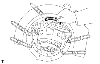
Using a plastic-faced hammer, tap on the ring gear to make sure the differential case is aligned with the carrier, and fit the bearings and plate washers into the carrier.
Tech Tips
If it is difficult to install the differential case to the carrier, replace the plate washer with a thinner one.
However, select a plate washer that allows no clearance between it and the carrier.
-
-
INSPECT DIFFERENTIAL RING GEAR BACKLASH
-
Using a dial indicator, measure the backlash while holding the side bearing of the ring gear side.
Standard backlash 0.10 to 0.20 mm (0.00394 to 0.00787 in.) -
Select a case cover side plate washer using the backlash as a reference.
Standard Side Plate Washer Thickness Mark No. Specified Condition Mark No. Specified Condition 01 2.66 to 2.68 mm (0.1048 to 0.1056 in.) 13 3.02 to 3.04 mm (0.1190 to 0.1198 in.) 02 2.69 to 2.71 mm (0.1060 to 0.1068 in.) 14 3.05 to 3.07 mm (0.1202 to 0.1210 in.) 03 2.72 to 2.74 mm (0.1072 to 0.1080 in.) 15 3.08 to 3.10 mm (0.1212 to 0.1220 in.) 04 2.75 to 2.77 mm (0.1084 to 0.1091 in.) 16 3.11 to 3.13 mm (0.1225 to 0.1233 in.) 05 2.78 to 2.80 mm (0.1095 to 0.1103 in.) 17 3.14 to 3.16 mm (0.1237 to 0.1245 in.) 06 2.81 to 2.83 mm (0.1107 to 0.1115 in.) 18 3.17 to 3.19 mm (0.1249 to 0.1257 in.) 07 2.84 to 2.86 mm (0.1119 to 0.1127 in.) 19 3.20 to 3.22 mm (0.1261 to 0.1269 in.) 08 2.87 to 2.89 mm (0.1131 to 0.1139 in.) 20 3.23 to 3.25 mm (0.1273 to 0.1281 in.) 09 2.90 to 2.92 mm (0.1143 to 0.1150 in.) 21 3.26 to 3.28 mm (0.1284 to 0.1292 in.) 10 2.93 to 2.95 mm (0.1154 to 0.1162 in.) 22 3.29 to 3.31 mm (0.1296 to 0.1304 in.) 11 2.96 to 2.98 mm (0.1166 to 0.1174 in.) 23 3.32 to 3.34 mm (0.1308 to 0.1316 in.) 12 2.99 to 3.01 mm (0.1178 to 0.1186 in.) - - -
Select a ring gear teeth side plate washer so that there is no clearance between the outer race and case.
-
Remove the 2 plate washers and differential carrier.
-
Install the selected plate washer into the lower part of the carrier.
-
Place the selected plate washer onto the differential case together with the outer races, and install the differential case with the outer races to the carrier.
-
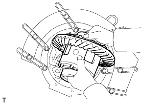
Using a plastic-faced hammer, tap on the ring gear to make sure the differential case is aligned with the carrier, and fit the bearings and plate washers into the carrier.
-
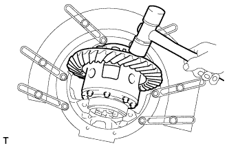
Using a dial indicator, measure the ring gear backlash.
Standard backlash 0.10 to 0.20 mm (0.00394 to 0.00787 in.) If the backlash is not within the specification, adjust it by either increasing or decreasing the thickness of washers on both sides by an equal amount.
Tech Tips
There should be no clearance between the plate washers and case.
-
Ensure that there is ring gear backlash.
-
-
ADJUST SIDE BEARING PRELOAD
-
Remove the ring gear side plate washer.
-
Using a micrometer, measure the thickness.
-
Using the backlash as a reference, select a washer that is 0.06 to 0.09 mm (0.00236 to 0.00354 in.) thicker than the removed washer.
Tech Tips
Select a washer which can be pressed in 2/3 of the full amount with your finger.
-
Install the selected plate washer.
-
Using SST and plastic-faced hammer, tap the plate washer so that it fits to the bearing.
- SST
- 09504-22011
-
Align the matchmarks on the caps and carrier.
-
Install the 4 bearing cap bolts to the specified torque.
- Torque:
- 113 N*m { 1150 kgf*cm, 83 ft.*lbf }
-
Using a dial indicator, adjust the ring gear backlash until it is within the specification.
Standard backlash 0.10 to 0.20 mm (0.00394 to 0.00787 in.)
-
-
INSPECT TOTAL PRELOAD
-
Using a torque wrench, measure the preload with the teeth of the drive pinion and ring gear in contact.
Standard total preload (at starting) Standard drive pinion preload plus 0.29 to 0.49 N*m (3 to 5 kgf*cm, 3 to 4 in.*lbf)
-
-
INSPECT TOOTH CONTACT BETWEEN RING GEAR AND DRIVE PINION
-
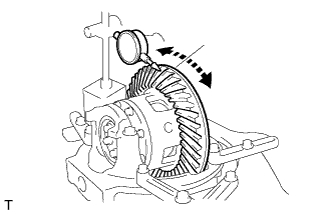
Coat 3 or 4 teeth at 3 different positions on the ring gear with Prussian blue.
-
Turn the companion flange in both directions to inspect the ring gear for proper tooth contact.
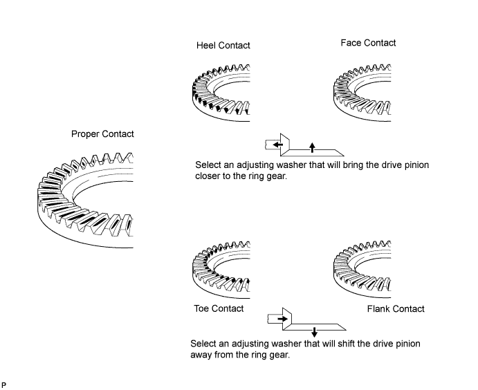
If the teeth are not contacting properly, use the following table to select a proper washer for correction.
Standard Washer Thickness Specified Condition Specified Condition 1.04 to 1.06 mm (0.0409 to 0.0417 in.) 1.315 to 1.335 mm (0.0518 to 0.0526 in.) 1.065 to 1.085 mm (0.0420 to 0.0427 in.) 1.34 to 1.36 mm (0.0528 to 0.0535 in.) 1.09 to 1.11 mm (0.0419 to 0.0437 in.) 1.365 to 1.385 mm (0.0537 to 0.0545 in.) 1.115 to 1.135 mm (0.0439 to 0.0447 in.) 1.39 to 1.41 mm (0.0547 to 0.0555 in.) 1.14 to 1.16 mm (0.0449 to 0.0457 in.) 1.415 to 1.435 mm (0.0558 to 0.0565 in.) 1.165 to 1.185 mm (0.0459 to 0.0467 in.) 1.44 to 1.46 mm (0.0567 to 0.0575 in.) 1.19 to 1.21 mm (0.0469 to 0.0476 in.) 1.465 to 1.485 mm (0.0577 to 0.0585 in.) 1.215 to 1.235 mm (0.0478 to 0.0486 in.) 1.49 to 1.51 mm (0.0587 to 0.0595 in.) 1.24 to 1.26 mm (0.0488 to 0.0496 in.) 1.515 to 1.535 mm (0.0597 to 0.0605 in.) 1.265 to 1.285 mm (0.0498 to 0.0506 in.) 1.54 to 1.56 mm (0.0607 to 0.0615 in.) 1.29 to 1.31 mm (0.0508 to 0.0516 in.) -
-
-
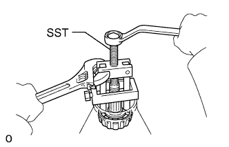
REMOVE DRIVE PINION COMPANION FLANGE REAR NUT
-
Using SST to hold the flange, remove the nut.
- SST
- 09330-00021 ( 09330-00030 )
-
-
REMOVE REAR DRIVE PINION REAR COMPANION FLANGE SUB-ASSEMBLY
-
Using SST, remove the companion flange.
- SST
- 09950-30012 ( 09951-03010, 09953-03010, 09954-03010, 09956-03030 )
-
-
REMOVE REAR DIFFERENTIAL DRIVE PINION OIL SLINGER
-
REMOVE REAR DRIVE PINION FRONT TAPERED ROLLER BEARING
-
Using SST, remove the bearing (inner race).
- SST
- 09556-22010
If the front bearing is damaged or worn, replace the bearing.
-
-
INSTALL REAR DIFFERENTIAL DRIVE PINION BEARING SPACER
-
Install a new spacer to the drive pinion.
-
-
INSTALL REAR DRIVE PINION FRONT TAPERED ROLLER BEARING
-
Using SST and a hammer, tap in the bearing (outer race).
- SST
- 09316-60011 ( 09316-00011, 09316-00021 )
-
Install the bearing (inner race).
-
-
INSTALL REAR DIFFERENTIAL DRIVE PINION OIL SLINGER
-
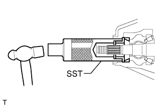
INSTALL REAR DIFFERENTIAL CARRIER OIL SEAL
-
Using SST and a hammer, tap in a new oil seal.
- SST
- 09214-76011
Standard oil seal depth 0.05 to 0.95 mm (0.00197 to 0.0374) -
Coat the lip of the oil seal with MP grease.
-
-
INSTALL REAR DRIVE PINION REAR COMPANION FLANGE SUB-ASSEMBLY
-
Using SST, install the companion flange.
- SST
- 09950-30012 ( 09951-03010, 09953-03010, 09954-03010, 09955-03030, 09956-03040 )
-
-
INSPECT DRIVE PINION PRELOAD
-
Coat the threads of a new nut with hypoid gear oil.
-
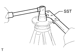
Using SST to hold the companion flange, install the nut by tightening it until the standard preload is reached.
- SST
- 09330-00021 ( 09330-00030 )
- Torque:
- 441 N*m { 4497 kgf*cm, 325 ft.*lbf, or less }
-
Using a torque wrench, measure the preload.
Standard Preload (at Starting) Bearing Specified Condition New 1.0 to 1.7 N*m (11 to 17 kgf*cm, 10 to 14 in.*lbf) Reused 0.9 to 1.4 N*m (9 to 13 kgf*cm, 8 to 12 in.*lbf)
-
-
INSPECT TOTAL PRELOAD
-
Using a torque wrench, measure the preload with the teeth of the drive pinion and ring gear in contact.
Standard total preload (at starting) Standard drive pinion preload plus 0.29 to 0.49 N*m (3 to 5 kgf*cm, 3 to 4 in.*lbf)
-
-
INSPECT DIFFERENTIAL RING GEAR BACKLASH
-
Using a dial indicator, measure the ring gear backlash.
Standard backlash 0.10 to 0.20 mm (0.00394 to 0.00787 in.) Tech Tips
Measure at 3 or more positions around the circumference of the ring gear.
If the backlash is not as specified, adjust the side bearing preload or repair as necessary.
-
-
INSPECT RUNOUT OF REAR DRIVE PINION REAR COMPANION FLANGE SUB-ASSEMBLY
-
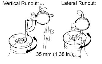
Using a dial indicator, measure the runout of the companion flange vertically and laterally.
Maximum Runout Runout Specified Condition Vertical runout 0.10 mm (0.00394 in.) Lateral runout 0.10 mm (0.00394 in.) If the runout is more than the maximum, replace the companion flange.
-
-
STAKE DRIVE PINION COMPANION FLANGE REAR NUT
-
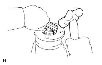
Using a chisel and hammer, stake the nut.
-
-
INSTALL DIFFERENTIAL LOCK SHIFT ACTUATOR
-
Remove any old FIPG material.
-
Clean the contact surfaces of any residual FIPG material using non-residue solvent.
-
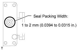
Apply seal packing to the actuator.
Seal packing Toyota Genuine Seal Packing 1281, Three Bond 1281 or equivalent Tech Tips
Install the actuator within 10 minutes after applying seal packing.
-
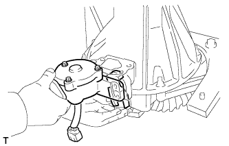
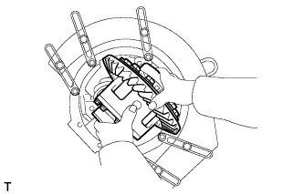
Install the shift fork and actuator to the differential and align the shift fork hole with the shift lock.
-
Clean the threads of the set bolt and fork shaft with non-residue solvent.
-
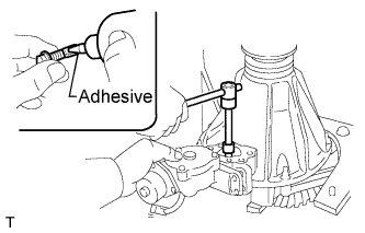
Coat the threads of the set bolt with adhesive.
Adhesive Toyota Genuine Adhesive 1324, Three Bond 1324 or equivalent -
Install the shift fork shaft set bolt.
- Torque:
- 20 N*m { 204 kgf*cm, 15 ft.*lbf }
-
Engage the sleeve with the dog clutch of the differential case.
-
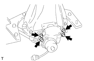
Install the 4 bolts.
- Torque:
- 24 N*m { 245 kgf*cm, 18 ft.*lbf }
-
-
INSTALL REAR DIFFERENTIAL LOCK COVER
-
Remove any old FIPG material.
-
Clean the contact surfaces of any residual FIPG material using non-residue solvent.
-
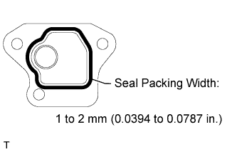
Apply seal packing to the cover
Seal packing Toyota Genuine Seal Packing 1281, Three Bond 1281 or equivalent Tech Tips
Install the cover within 10 minutes after applying seal packing.
-
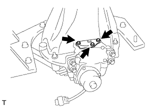
Install the cover with the 3 bolts.
- Torque:
- 18 N*m { 184 kgf*cm, 13 ft.*lbf }
-
-
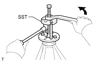
INSTALL NO. 1 TRANSFER INDICATOR SWITCH
-
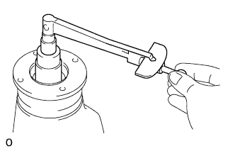
Using a SST, install a new gasket and the indicator switch.
- SST
- 09922-10010
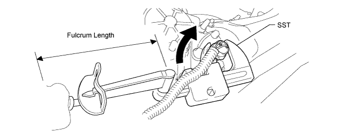
- Torque:
- without SST
- 40 N*m { 408 kgf*cm, 30 ft.*lbf }
- with SST
- 28 N*m { 283 kgf*cm, 20 ft.*lbf }
Note
-
Rotate SST in the direction shown in the illustration.
-
Use a torque wrench with a fulcrum length of 300 mm (11.8 in.).
-
Connect the connector.
-