REAR AXLE SHAFT REMOVAL

Tech Tips
-
Use the same procedures for the LH side and RH side.
-
The procedures listed below are for the LH side.
-
REMOVE STABILIZER CONTROL VALVE PROTECTOR (w/ KDSS)
-
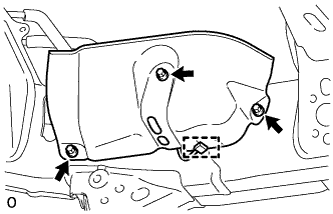
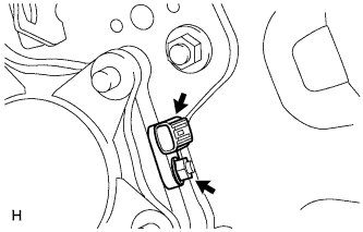
Detach the clamp, and disconnect the connector from the protector.
-
Remove the 3 bolts and protector.
-
-
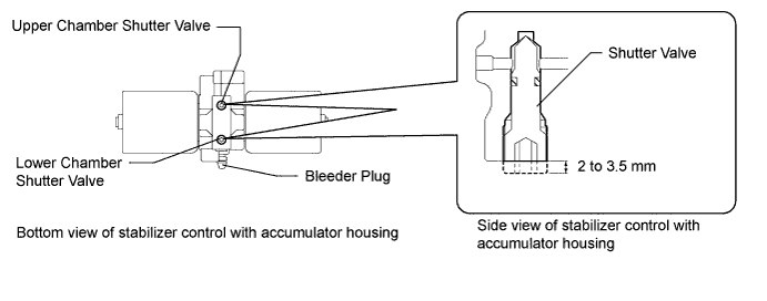
OPEN STABILIZER CONTROL WITH ACCUMULATOR HOUSING SHUTTER VALVE (w/ KDSS)
-
Using a 5 mm hexagon socket wrench, loosen the lower and upper chamber shutter valves of the stabilizer control with accumulator housing 2.0 to 3.5 turns.
Note
-
When loosening a shutter valve, make sure that the end protrudes 2 to 3.5 mm (0.0787 to 0.137 in.) from the surface of the block, and do not turn the shutter valve any further.
-
Do not remove the shutter valves.
-
-
-
REMOVE REAR WHEEL LH
-
DRAIN BRAKE FLUID
Note
Wash off brake fluid immediately if it comes in contact with any painted surface.
-
DISCONNECT REAR BRAKE FLEXIBLE HOSE
-
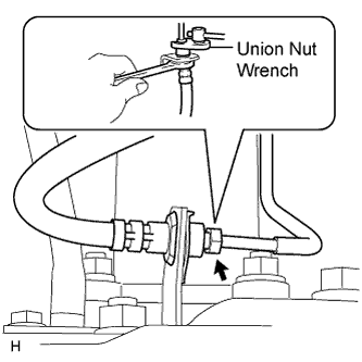
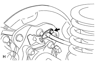
Disconnect the brake tube from the flexible hose with SST while holding the flexible hose with a wrench.
Note
-
Do not bend or damage the brake tube.
-
Do not allow any foreign matter such as dirt and dust to enter the brake tube from the connecting point.
-
-
Remove the clip.
-
-
DISCONNECT REAR DISC BRAKE CYLINDER ASSEMBLY LH
-
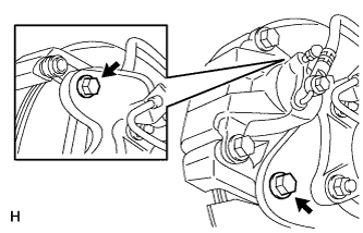
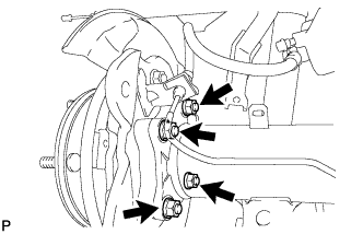
Remove the 2 bolts and disconnect the rear disc brake cylinder.
Note
-
Do not twist or bend the flexible hose.
-
Do not disconnect the flexible hose from the disc brake cylinder.
-
-
-
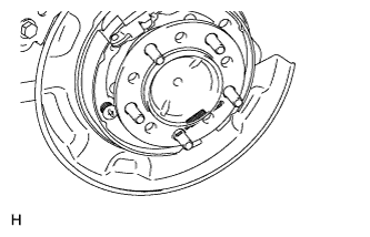
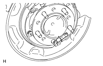
REMOVE REAR DISC LH
-
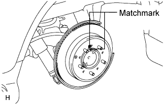
Put matchmarks on the rear disc and axle hub if planning to reuse the disc.
-
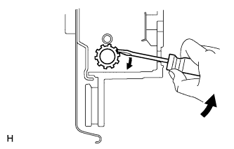
Turn the shoe adjuster as shown in the illustration until the disc turns freely, and then remove the disc.
-
-
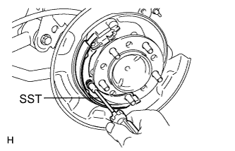
REMOVE PARKING BRAKE SHOE RETURN TENSION SPRING LH
-
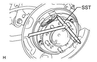
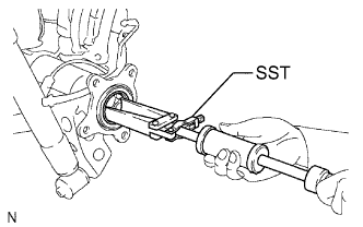
Using SST, remove the return spring.
- SST
- 09703-30011
-
-
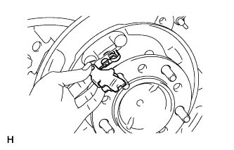
REMOVE NO. 1 PARKING BRAKE SHOE ASSEMBLY LH
-
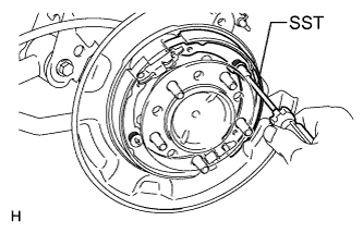
Using SST, remove the shoe hold down spring cup, compression spring and shoe hold down spring pin.
- SST
- 09718-00011
-
Disconnect the tension spring from the No. 1 parking brake shoe.
-
Remove the No. 1 parking brake shoe and shoe adjuster screw set.
-
-
REMOVE NO. 2 PARKING BRAKE SHOE ASSEMBLY LH
-
Using SST, remove the shoe hold down spring cup, compression spring and shoe hold down spring pin.
- SST
- 09718-00011
-
Remove the No. 2 parking brake shoe.
-
-
REMOVE PARKING BRAKE SHOE LEVER SUB-ASSEMBLY LH
-
Disconnect the No. 3 parking brake cable from the parking brake shoe lever.
-
Remove the parking brake shoe lever.
-
-
DISCONNECT NO. 3 PARKING BRAKE CABLE ASSEMBLY
-
Remove the bolt and No. 3 parking brake cable.
-
-
DISCONNECT REAR SPEED SENSOR LH
-
Install the speed sensor with the nut.
- Torque:
- 8.3 N*m { 85 kgf*cm, 73 in.*lbf }
Note
-
Make sure there are no pieces of iron or other foreign matter attached to the sensor tip.
-
While inserting the speed sensor into the knuckle hole, do not strike or damage the sensor tip.
-
After installing the speed sensor, make sure there is no clearance or foreign matter between the sensor stay part and the knuckle.
-
Make sure there is no foreign matter attached to the speed sensor rotor.
-
-
REMOVE REAR AXLE SHAFT LH
-
Remove the 4 nuts and rear axle shaft together with the parking brake plate.
-
Remove the O-ring.
-
-
REMOVE REAR AXLE SHAFT OIL SEAL LH
-
Using SST, tap out the oil seal.
- SST
- 09308-00010
Note
Be careful not to damage the axle housing hole.
-