FRONT AXLE HUB INSTALLATION

Tech Tips
-
Use the same procedures for the LH side and RH side.
-
The procedures listed below are for the LH side.
-
INSTALL FRONT AXLE HUB SUB-ASSEMBLY LH
-
Apply MP grease to a new O-ring.
-
Install the O-ring to the axle hub.
Note
Do not damage the O-ring.
-
Connect the front drive shaft to the front axle hub.
Note
Be careful not to damage the front drive shaft boot.
-
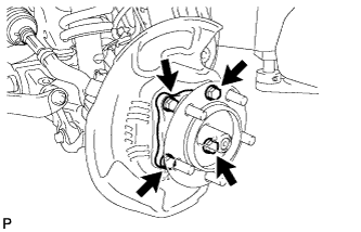
Install the dust cover and axle hub to the steering knuckle with the 4 bolts.
- Torque:
- 99 N*m { 1010 kgf*cm, 73 ft.*lbf }
-
-
INSTALL FRONT DISC
-
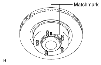
Align the matchmarks, and then install the front disc.
Tech Tips
When replacing the front disc with a new one, select the installation position where the front disc has the minimum runout.
-
-
CONNECT FRONT DISC BRAKE CALIPER ASSEMBLY LH
-
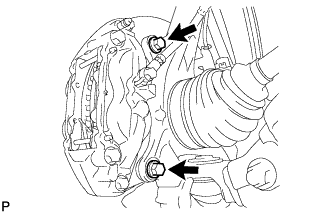
Connect the front disc brake caliper and install 2 new bolts.
- Torque:
- 99 N*m { 1010 kgf*cm, 73 ft.*lbf }
Note
-
Do not twist the flexible hose.
-
Make sure that the bolts are free from damage and foreign matter.
-
Do not overtighten the bolts.
-
-
INSTALL FRONT AXLE SHAFT NUT LH
-
Clean the threaded parts on the drive shaft and axle shaft nut using a non-residue solvent.
Note
-
Be sure to perform this work for a new drive shaft.
-
Keep the threaded parts free of oil and foreign objects.
-
-
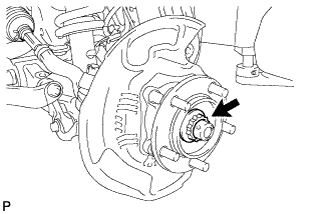
Using a 39 mm socket wrench, install the axle shaft nut.
- Torque:
- 200 N*m { 2039 kgf*cm, 148 ft.*lbf }
-
Using a 39 mm socket wrench, loosen the axle shaft nut.
-
Using a 39 mm socket wrench, retighten the axle shaft nut.
- Torque:
- 340 N*m { 3467 kgf*cm, 251 ft.*lbf }
-
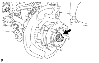
Install the front wheel adjusting lock cap and a new cotter pin.
-
-
DISCONNECT FRONT DISC BRAKE CALIPER ASSEMBLY LH
-
Remove the 2 bolts and disconnect the disc brake caliper from the steering knuckle.
Note
-
Do not disconnect the flexible hose from the disc brake caliper.
-
Do not twist or bend the flexible hose.
-
-
-
REMOVE FRONT DISC
-
Put matchmarks on the front disc and axle hub if planning to reuse the disc.
-
Remove the front disc.
-
-
INSPECT FRONT AXLE HUB
-
Inspect the front axle hub Click here.
-
-
INSTALL FRONT AXLE HUB GREASE CAP LH
-
Install the axle hub grease cap.
Note
Make sure to securely fit the grease cap to the axle hub.
-
-
INSTALL FRONT DISC
-
Align the matchmarks, and then install the front disc.
Tech Tips
When replacing the front disc with a new one, select the installation position where the front disc has the minimum runout.
-
-
CONNECT FRONT DISC BRAKE CALIPER ASSEMBLY LH
-
Connect the front disc brake caliper and install 2 new bolts.
- Torque:
- 99 N*m { 1010 kgf*cm, 73 ft.*lbf }
Note
-
Do not twist the flexible hose.
-
Make sure that the bolts are free from damage and foreign matter.
-
Do not overtighten the bolts.
-
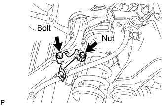
Connect the brake tube bracket to the steering knuckle with the bolt and nut.
- Torque:
- for bolt
- 31 N*m { 316 kgf*cm, 23 ft.*lbf }
- for nut
- 13 N*m { 132 kgf*cm, 10 ft.*lbf }
-
-
INSTALL FRONT WHEEL
- Torque:
- for Aluminum Wheel
- 131 N*m { 1336 kgf*cm, 97 ft.*lbf }
- for Steel Wheel
- 209 N*m { 2131 kgf*cm, 154 ft.*lbf }
-
MEASURE VEHICLE HEIGHT (w/ KDSS)
Note
-
Perform the inspection on a level surface.
-
Ensure that the wheels are on the ground and facing straight ahead.
-
Perform the inspection with the vehicle load completely on the suspension.
Tech Tips
-
Perform this step with the fuel tank full.
-
If there are any parts installed to the vehicle which place any unbalanced load on the left or right side of the vehicle, remove them.
-
Set the tire pressure to the specified value(s) Click here.
-
Bounce the vehicle to stabilize the suspension.
-
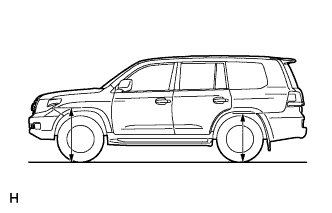
Measure the distance from the ground to the top of the bumper and calculate the difference in the vehicle height between left and right. Perform this procedure for both the front and rear wheels.
Height difference of left and right sides 15 mm (0.591 in.) or less Tech Tips
If not as specified, perform the vehicle tilt calibration.
-
-
CLOSE STABILIZER CONTROL WITH ACCUMULATOR HOUSING SHUTTER VALVE (w/ KDSS)
Note
-
Perform the inspection on a level surface.
-
Ensure that the wheels are on the ground and facing straight ahead.
-
Perform the inspection with the vehicle load completely on the suspension.
Tech Tips
-
Perform this step with the fuel tank full.
-
If there are any parts installed to the vehicle which place any unbalanced load on the left or right side of the vehicle, remove them.
-
Using a 5 mm hexagon socket wrench, tighten the lower and upper chamber shutter valves of the stabilizer control with accumulator housing.
- Torque:
- 14 N*m { 143 kgf*cm, 10 ft.*lbf }
-
-
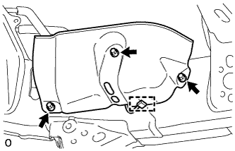
INSTALL STABILIZER CONTROL VALVE PROTECTOR (w/ KDSS)
-
Install the valve protector with the 3 bolts.
- Torque:
- 18 N*m { 184 kgf*cm, 13 ft.*lbf }
-
Attach the clamp, and connect the connector to the valve protector.
-
-
CHECK SPEED SENSOR SIGNAL
-
w/ VSC:
-
w/ ABS:
-