PROPELLER SHAFT ASSEMBLY DISASSEMBLY

Note
Be careful not to grip the propeller shaft tube too tightly in a vise as this will cause deformation.
-
CLEAN PROPELLER SHAFT GREASE
-
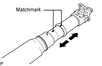
Place matchmarks on the propeller shaft and sleeve yoke.
-
Disconnect the sleeve yoke from the propeller shaft.
-
Clean off any grease on the spline.
-
-
REMOVE REAR PROPELLER SHAFT UNIVERSAL JOINT SPIDER ASSEMBLY
-
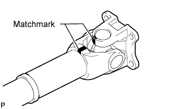
Place matchmarks on the flange yoke and sleeve yoke or propeller shaft.
-
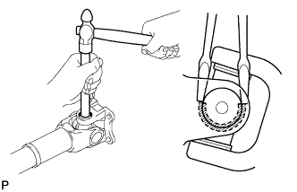
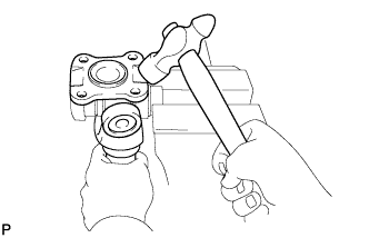
Using a brass bar and hammer, slightly tap in the spider bearing outer races.
-
Using 2 screwdrivers, remove the 4 snap rings from the grooves.
-
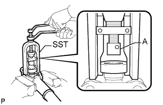
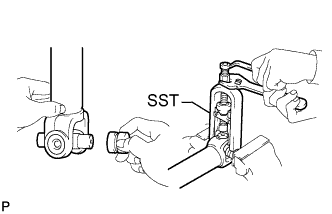
Using SST, push out the bearing from the flange.
- SST
- 09332-25010
Tech Tips
Before installing SST, sufficiently raise the part labeled A. If part A is too low, SST may be difficult to install.
-
Clamp the bearing outer race in a vise and tap off the flange with a hammer.
Tech Tips
Remove the bearing on the opposite side using the same procedure.
-
Remove the flange yoke from the sleeve yoke (or propeller shaft).
-
Install the 2 removed bearing outer races to the spider.
-
Using SST, push out the bearing from the yoke.
- SST
- 09332-25010
-
Clamp the outer bearing race in a vise and tap off the yoke with a hammer.
Tech Tips
Remove the bearing on the opposite side using the same procedure.
-