TRANSFER ASSEMBLY REASSEMBLY

Tech Tips
Coat all of the sliding and rotating surfaces with gear oil before reassembly.
-
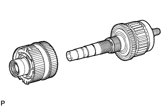
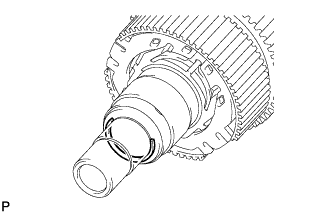
INSTALL REAR TRANSFER OUTPUT SHAFT
-
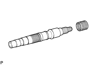
Install a new needle roller bearing.
-
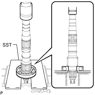
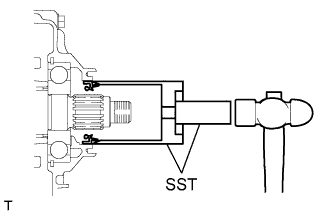
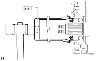
Using SST and a press, press in a new bearing.
- SST
- 09527-10011
Note
Set the snap ring groove of the bearing to the front side.
-
-
INSTALL TRANSFER DRIVE SPROCKET BEARING
-
Install the bearing to the output shaft.
-
-
INSTALL TRANSFER DRIVE SPROCKET SUB-ASSEMBLY
-
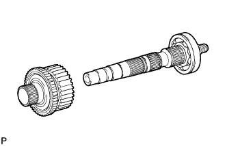
Install the drive sprocket to the output shaft.
-
-
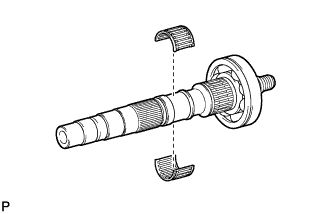
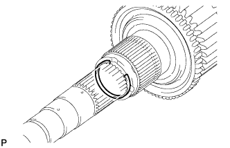
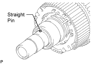
INSTALL TRANSFER OUTPUT SHAFT SPACER
-
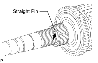
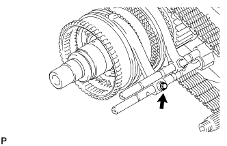
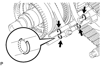
Install the straight pin to the output shaft.
-
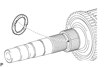
Align the straight pin with the straight pin groove of the output shaft spacer, and slide on the output shaft spacer.
-
Using a screwdriver and hammer, tap on the snap ring.
-
-
INSPECT TRANSFER DRIVE SPROCKET SUB-ASSEMBLY
-
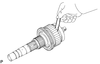
Using a feeler gauge, measure the drive sprocket thrust clearance.
Standard Clearance 0.10 to 0.47 mm (0.00394 to 0.0185 in.) Maximum Clearance 0.47 mm (0.0185 in.) If the clearance is more than the maximum, replace the drive sprocket sub-assembly.
-
-
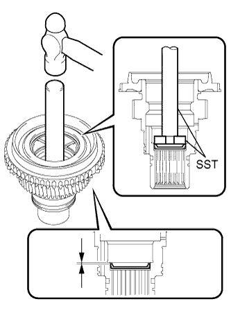
INSTALL CENTER DIFFERENTIAL CASE
-
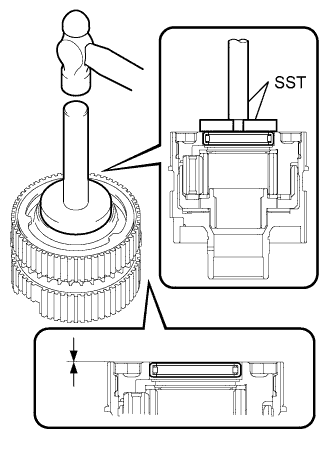
Using SST and a hammer, tap in a new needle roller bearing until its surface is 0 to 0.5 mm (0 to 0.0197 in.) from the center differential case upper surface.
- SST
- 09950-60020 ( 09951-00710 )
- 09950-70010 ( 09951-07100 )
Note
-
Be careful not to damage the center differential case.
-
Install the bearing so that the mark is on the outside.
-
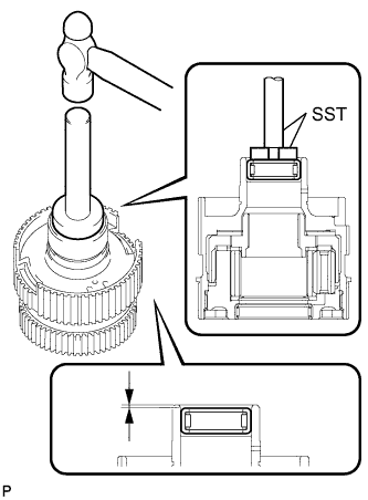
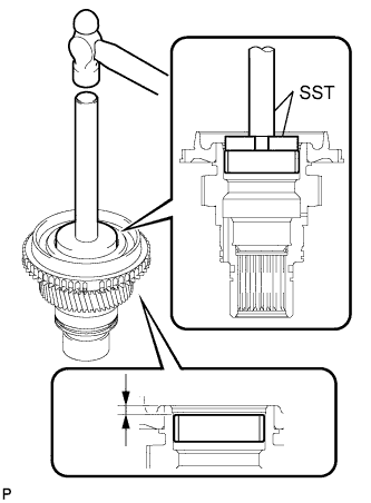
Using SST and a hammer, tap in a new needle roller bearing until its surface is 1.5 to 2.0 mm (0.0591 to 0.0787 in.) from the center differential case upper surface.
- SST
- 09950-60010 ( 09951-00460 )
- 09950-70010 ( 09951-07100 )
Note
-
Be careful not to damage the center differential case.
-
Install the bearing so that the mark is on the outside.
-
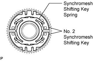
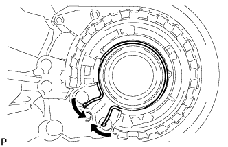
for Manual Transmission:
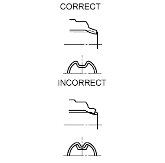
Install the synchromesh shifting key spring and No. 2 synchromesh shifting keys as shown in the illustration.
-
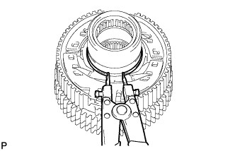
for Manual Transmission:
Using a snap ring expander, install the snap ring.
-
Install the center differential case to the output shaft.
-
-
INSTALL NO. 1 TRANSFER OUTPUT SHAFT SPACER
-
Install the straight pin to the output shaft.
-
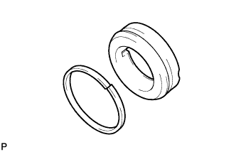
Install a new seal ring to the output shaft spacer.
-
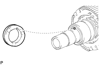
Align the pin with the straight pin groove of the output shaft spacer, and slide on the output shaft spacer.
-
Using a screwdriver and hammer, tap on the snap ring.
-
-
INSTALL TRANSFER OUTPUT SHAFT WASHER
-
Install the 2 output shaft washers to the output shaft.
-
-
INSTALL TRANSFER INPUT SHAFT PLUG
-
Using SST and a hammer, tap in a new input shaft plug until its surface is 1.0 to 1.8 mm (0.0394 to 0.0709 in.) from the input shaft upper surface.
- SST
- 09950-60010 ( 09951-00410 )
- 09950-70010 ( 09951-07150 )
Note
Be careful not to damage or deform the input shaft plug when tapping it.
-
-
INSTALL TRANSFER INPUT SHAFT BIMETAL FORMED BUSH
-
Using SST and a hammer, tap in a new bush until its surface is 5.5 to 5.9 mm (0.217 to 0.232 in.) from the input shaft upper surface.
- SST
- 09950-70010 ( 09951-07150 )
- 09950-60010 ( 09951-00610 )
Note
Be careful not to damage the input shaft.
-
-
INSTALL TRANSFER INPUT SHAFT BEARING
-
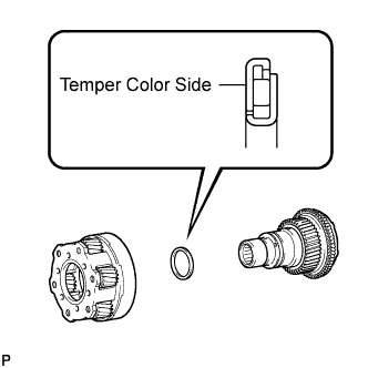
Install the low planetary gear bearing and low planetary gear to the input shaft.
Note
-
Make sure the low planetary gear bearing is installed in the correct direction.
-
Install the low planetary gear bearing so that its temper color side faces the low planetary gear.
-
-
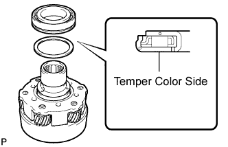
Install the low planetary gear bearing and a new input shaft bearing to the input shaft.
Note
-
Make sure the input shaft bearing is installed in the correct direction.
-
Make sure the low planetary gear bearing is installed in the correct direction.
-
Install the low planetary gear bearing so that its temper color side faces the low planetary gear.
-
-
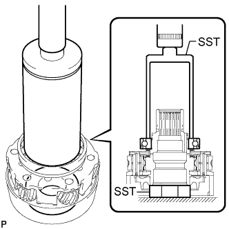
Using SST and a press, press in the bearing.
- SST
- 09513-36040
- 09515-21010
Note
After press-fitting the bearing to the input shaft, check that the bearing moves smoothly.
-
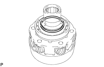
Select a snap ring that allows for minimum axial play and install it to the shaft.
Standard Snap Ring Thickness Mark Specified Condition C 2.13 to 2.18 mm (0.0839 to 0.0858 in.) D 2.18 to 2.23 mm (0.0858 to 0.0878 in.) E 2.23 to 2.28 mm (0.0878 to 0.0898 in.) F 2.28 to 2.33 mm (0.0898 to 0.0917 in.) G 2.33 to 2.38 mm (0.0917 to 0.0937 in.) H 2.38 to 2.43 mm (0.0937 to 0.0957 in.) J 2.43 to 2.48 mm (0.0957 to 0.0976 in.) -
Using a snap ring expander, install the snap ring.
Note
Make sure that the snap ring is firmly installed to the groove.
-
-
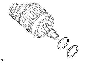
INSTALL NO. 1 TRANSFER INPUT SHAFT SEAL RING
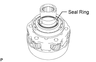
-
Apply transfer oil to a new seal ring.
-
Install a new seal ring to the input shaft.
-
-
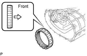
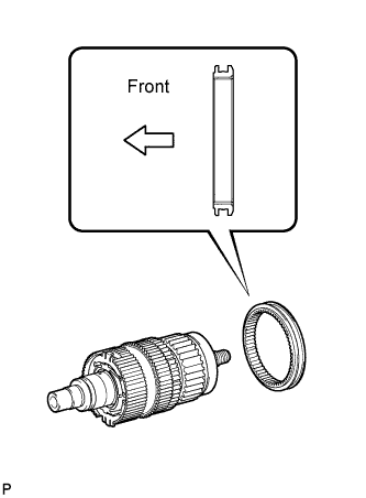
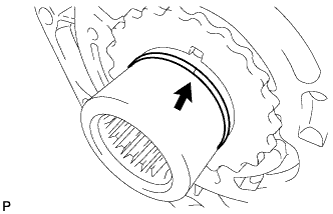
INSTALL TRANSFER DRIVEN SPROCKET BEARING
-
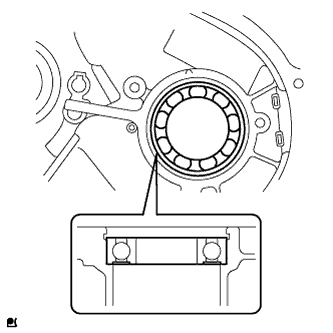
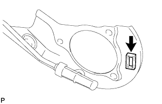
Install a new bearing to the front transfer case in the direction shown in the illustration.
Note
Make sure the bearing is installed in the correct direction.
-
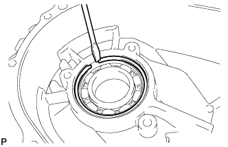
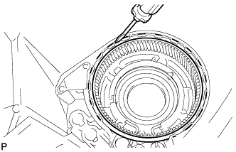
Using a screwdriver, install the snap ring.
-
-
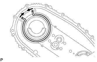
INSTALL TRANSFER LOW PLANETARY RING GEAR
-
Using a snap ring expander, install the snap ring to the front transfer case.
-
Install the low planetary ring gear to the front transfer case.
Note
Make sure to install the low planetary ring gear in the correct direction.
-
Using a screwdriver, install the snap ring.
Note
Make sure that the snap ring is firmly installed to the groove.
-
-
INSTALL INPUT SHAFT ASSEMBLY
-
While expanding the snap ring, install the input shaft to the front transfer case.
-
Apply adhesive to the threads of the 2 case plugs.
Adhesive Toyota Genuine Adhesive 1344, Three Bond 1344 or equivalent Note
Install the plugs within 3 minutes of application.
-
Using a 14 mm hexagon wrench, install the 2 case plugs.
- Torque:
- 37 N*m { 377 kgf*cm, 27 ft.*lbf }
-
-
INSTALL TRANSFER CASE MAGNET
-
Install the magnet to the oil separator.
-
-
INSTALL TRANSFER OIL SEPARATOR SUB-ASSEMBLY
-
Install a new O-ring to the oil separator.
-
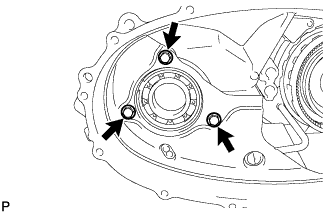
Install the oil separator with the 3 bolts.
- Torque:
- 18 N*m { 178 kgf*cm, 13 ft.*lbf }
-
-
INSTALL SIDE GEAR SHAFT HOLDER BEARING
-
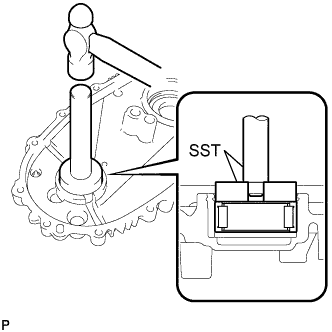
Using SST and a hammer, tap in a new bearing to the rear transfer case.
- SST
- 09950-60010 ( 09951-00590 )
- 09950-70010 ( 09951-07100 )
-
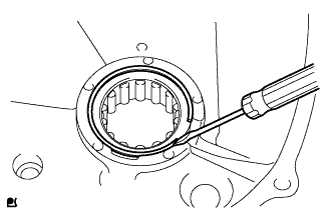
Using a screwdriver, install the snap ring.
-
-
INSTALL FRONT DRIVE CLUTCH SLEEVE
-
Apply gear oil to the connecting areas of the clutch sleeve and center differential case.
-
Install the clutch sleeve onto the output shaft.
Note
Make sure that the clutch sleeve is installed facing the correct direction.
-
-
INSTALL REAR TRANSFER OUTPUT SHAFT ASSEMBLY
-
Install the snap ring to the rear transfer case.
-
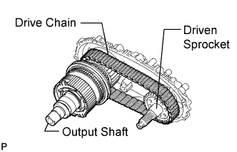
Install the output shaft, drive chain and driven sprocket.
Note
Do not drop the output shaft washers.
-
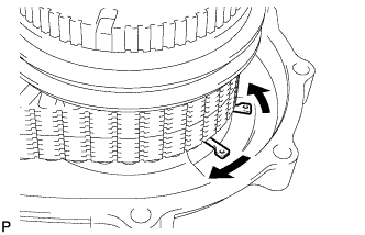
Using a snap ring expander, install the snap ring to the output shaft.
Note
Make sure that the snap ring is firmly installed to the groove.
-
-
INSTALL TRANSFER SHIFT ACTUATOR ASSEMBLY
-
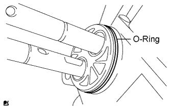
Install a new O-ring to the shift actuator.
-
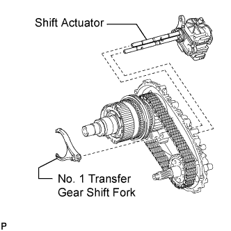
Set the No. 1 gear shift fork to the front drive clutch sleeve.
-
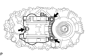
Install the shift actuator to the rear transfer case with the 3 bolts.
- Torque:
- 20 N*m { 204 kgf*cm, 15 ft.*lbf }
-
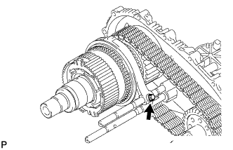
Install the No. 1 gear shift fork to the shift actuator with the bolt.
- Torque:
- 24 N*m { 245 kgf*cm, 18 ft.*lbf }
-
-
INSTALL NO. 2 TRANSFER GEAR SHIFT FORK
-
Set the No. 2 gear shift fork together with the high and low clutch sleeve to the shift actuator.
-
Install the No. 2 gear shift fork to the shift actuator with the bolt.
- Torque:
- 24 N*m { 245 kgf*cm, 18 ft.*lbf }
-
Using a screwdriver and hammer, tap the 4 shift fork shaft snap rings onto the shift fork shaft.
-
-
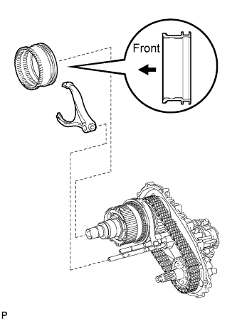
INSTALL FRONT TRANSFER OUTPUT SHAFT NEEDLE ROLLER BEARING
-
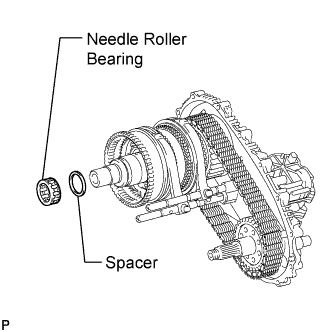
Install the needle roller bearing and spacer to the output shaft.
-
-
INSTALL NO. 1 SYNCHRONIZER RING (for Manual Transmission)
-
Align the protrusion of the synchronizer ring with the notch on the differential case and install it.
-
-
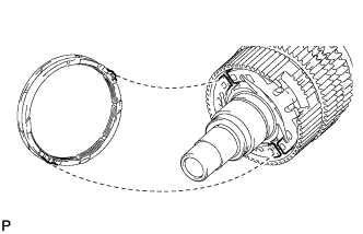
INSTALL REAR TRANSFER CASE ASSEMBLY
-
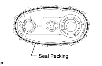
Apply seal packing to the rear transfer case as shown in the illustration.
Seal Packing Toyota Genuine Seal Packing 1281, Three Bond 1281 or equivalent Note
If the removed rear transfer case will be reused: After removing the rear transfer case, be sure to perform the following before reinstalling it: 1) using a knife, cut off any old FIPG on the rear transfer case contact surface, 2) clean off any remaining old FIPG from the rear transfer case contact surface, and 3) reapply seal packing to the rear transfer case.
-
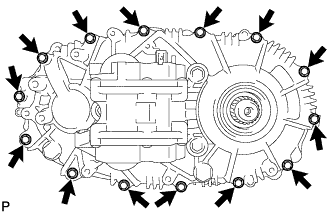
Install the rear transfer case with the 14 bolts.
- Torque:
- 28 N*m { 286 kgf*cm, 21 ft.*lbf }
Note
Tighten the bolts within 10 minutes of applying the seal packing. The seal packing will dry very quickly.
-
-
INSTALL TRANSFER CASE PLUG
-
Apply adhesive to the threads of the plug.
Adhesive Toyota Genuine Adhesive 1344, Three Bond 1344 or equivalent Note
Install the plug within 3 minutes of application.
-
Using a 6 mm hexagon wrench, install the plug.
- Torque:
- 39 N*m { 400 kgf*cm, 29 ft.*lbf }
-
-
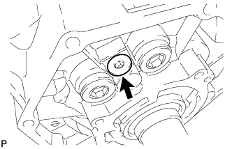
INSTALL NO. 1 TRANSFER CASE PLUG
-
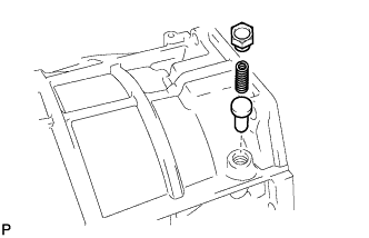
Install the pin and compression spring to the front transfer case.
-
Apply adhesive to the threads of the plug.
Adhesive Toyota Genuine Adhesive 1344, Three Bond 1344 or equivalent Note
Install the plug within 3 minutes of application.
-
Install the plug.
- Torque:
- 19 N*m { 190 kgf*cm, 14 ft.*lbf }
-
-
INSTALL TRANSFER CASE REAR OIL SEAL
-
Apply transfer oil to the spline of the output shaft.
-
Using SST and a hammer, tap in a new oil seal until its surface is flush with the housing upper surface.
- SST
- 09649-17010
- 09950-70010 ( 09951-07150 )
-
-
INSTALL REAR OUTPUT SHAFT COMPANION FLANGE SUB-ASSEMBLY
-
Install the companion flange onto the output shaft.
-
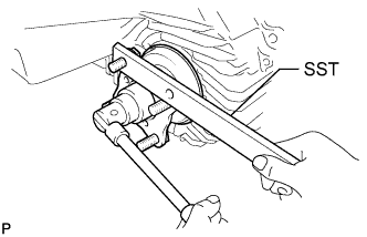
Using SST to hold the companion flange, install a new O-ring and a new companion flange lock nut.
- SST
- 09330-00021
- Torque:
- 127 N*m { 1299 kgf*cm, 94 ft.*lbf }
-
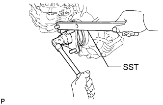
Using a chisel and hammer, stake the companion flange lock nut.
-
-
INSTALL TRANSFER CASE FRONT OIL SEAL
-
Apply transfer oil to the spline of the driven sprocket.
-
Using SST and a hammer, tap in a new front transfer case oil seal.
- SST
- 09613-26010
Note
The front transfer case oil seal should be installed completely.
-
-
INSTALL TRANSFER OUTPUT SHAFT DUST DEFLECTOR
-
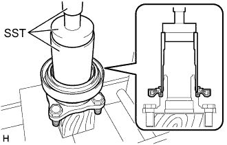
Using SST and a press, install a new transfer output shaft dust deflector.
- SST
- 09523-36010
- 09950-60010 ( 09951-00460, 09951-00560, 09952-06010 )
- 09950-70010 ( 09951-07100 )
Note
-
Be careful not to damage the transfer output shaft dust deflector and front output shaft companion flange sub-assembly.
-
The transfer output shaft dust deflector should be installed completely.
-
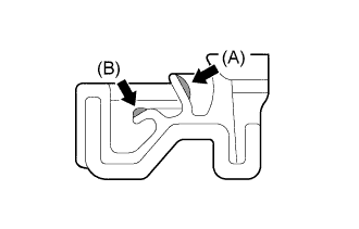
Apply MP grease to the transfer output shaft dust deflector lip.
Standard Grease Capacity Location A 0.4 to 0.6 g (0.015 to 0.021 oz.) Location B 0.1 g (0.0004 oz.)
-
-
INSTALL FRONT OUTPUT SHAFT COMPANION FLANGE SUB-ASSEMBLY
-
Install the companion flange onto the drive sprocket.
-
Using SST to hold the companion flange, install a new O-ring and a new companion flange lock nut.
- SST
- 09330-00021
- Torque:
- 127 N*m { 1299 kgf*cm, 94 ft.*lbf }
-
Using a chisel and hammer, stake the companion flange lock nut.
-
-
INSTALL TRANSFER OIL PUMP PLATE OIL SEAL
-
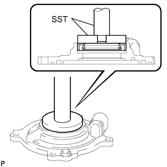
Using SST and a hammer, tap in a new oil seal until its surface is flush with the oil pump plate upper surface.
- SST
- 09950-60020 ( 09951-00680 )
- 09950-70010 ( 09951-07100 )
Note
Be careful not to damage the oil pump plate.
-
-
INSTALL TRANSFER CASE PLUG
-
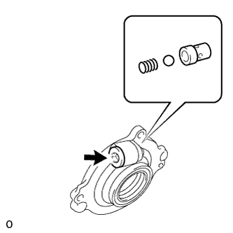
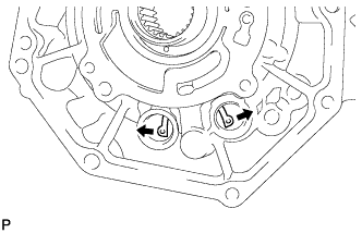
Install the relief valve seat, ball and compression spring to the oil pump plate.
-
Apply adhesive to the threads of the plug.
Adhesive Toyota Genuine Adhesive 1344, Three Bond 1344 or equivalent Note
Install the plug within 3 minutes of application.
-
Using a 10 mm hexagon wrench, install the plug.
- Torque:
- 29 N*m { 300 kgf*cm, 22 ft.*lbf }
-
-
INSTALL TRANSFER CASE STRAIGHT PIN
-
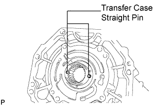
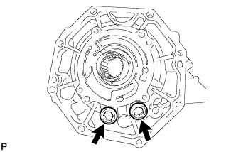
Install the 2 straight pins to the input shaft.
-
-
INSTALL TRANSFER OIL PUMP PLATE
-
Apply transfer oil to a new O-ring, drive rotor, driven rotor and a new transfer oil seal ring.
-
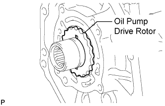
Install the drive rotor to the input shaft.
-
Install the transfer oil seal ring to the input shaft.
-
Install the O-ring to the oil pump plate.
-
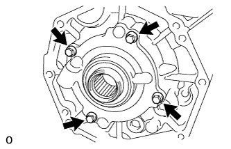
Install the oil pump plate and driven rotor to the front transfer case with the 4 bolts.
- Torque:
- 12 N*m { 117 kgf*cm, 9 ft.*lbf }
-
-
INSTALL PROPELLER SHAFT HEAT INSULATOR BRACKET SUB-ASSEMBLY
-
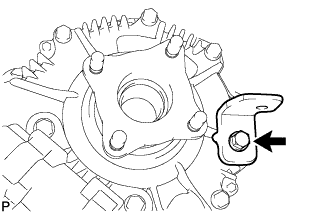
Install the bracket to the rear transfer case with the bolt.
- Torque:
- 20 N*m { 204 kgf*cm, 15 ft.*lbf }
-