OUTPUT SHAFT REASSEMBLY

-
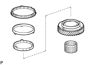
INSTALL NO. 2 TRANSMISSION HUB SLEEVE
-
Apply a light coat of gear oil to the No. 2 transmission hub sleeve and No. 2 transmission clutch hub.
-
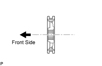
Install the No. 2 transmission hub sleeve and 3 shifting keys to the No. 2 transmission clutch hub.
Note
Do not mistake the installation direction of the No. 2 transmission hub sleeve and No. 2 transmission clutch hub.
-
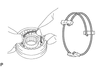
Insert the 2 springs under the shifting keys.
Note
Position the key springs so that their end gaps are not aligned.
-
-
INSTALL NO. 3 TRANSMISSION HUB SLEEVE
-
Apply a light coat of gear oil to the No. 3 transmission hub sleeve and No. 3 transmission clutch hub.
-
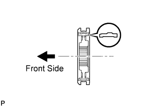
Install the No. 3 transmission hub sleeve and 3 shifting keys to the No. 3 transmission clutch hub.
Note
Do not mistake the installation direction of the No. 3 transmission hub sleeve, No. 3 transmission clutch hub, and shifting keys.
-
Insert the 2 springs under the shifting keys.
Note
Position the key springs so that their end gaps are not aligned.
-
-
INSTALL NO. 1 TRANSMISSION HUB SLEEVE
-
Apply a light coat of gear oil to the No. 1 transmission hub sleeve and No. 1 transmission clutch hub.
-
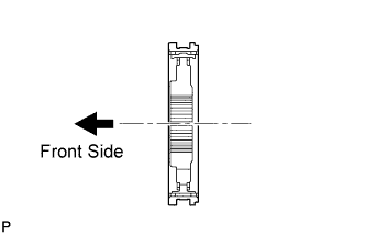
Install the No. 1 transmission hub sleeve and 3 shifting keys to the No. 1 transmission clutch hub.
Note
Do not mistake the installation direction of the No. 1 transmission hub sleeve and No. 1 transmission clutch hub.
-
Insert the 2 springs under the shifting keys.
Note
Position the key springs so that their end gaps are not aligned.
-
-
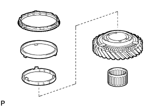
INSTALL 5TH COUNTER GEAR BEARING
-
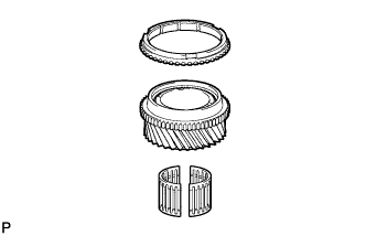
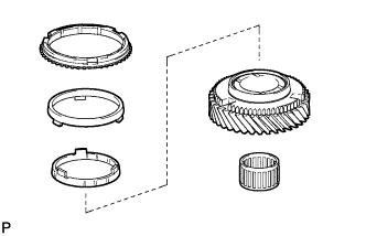
Coat the 5th counter gear bearing with gear oil, then install it to the 5th gear.
-
-
INSTALL 5TH GEAR
-
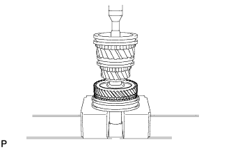
Coat the 5th gear and No. 3 synchronizer ring with gear oil, and set them onto the output shaft.
-
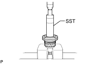
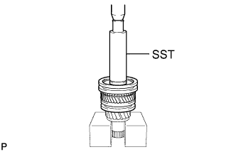
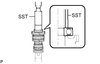
Using SST and a press, install the 5th gear, No. 3 synchronizer ring and transmission hub sleeve to the output shaft.
- SST
- 09316-60011 ( 09316-00011 )
Tech Tips
Align the convex portion of the synchronizer ring with the groove of the transmission hub sleeve.
-
Check that the 5th gear, No. 3 synchronizer ring, and transmission hub sleeve move smoothly.
-
-
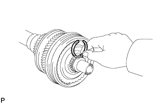
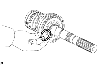
INSTALL NO. 3 TRANSMISSION CLUTCH HUB SHAFT SNAP RING
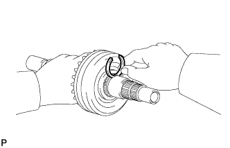
-
Select a new snap ring that will allow minimum clearance.
Standard Clearance 0.1 mm (0.00393 in.) or less Snap Ring Thickness Part No. Thickness Mark 90520-34018 2.40 to 2.45 mm
(0.0945 to 0.0965 in.)
A 90520-34019 2.45 to 2.50 mm
(0.0965 to 0.0984 in.)
B 90520-34020 2.50 to 2.55 mm
(0.0984 to 0.100 in.)
C 90520-34021 2.55 to 2.60 mm
(0.100 to 0.102 in.)
D 90520-34022 2.60 to 2.65 mm
(0.102 to 0.104 in.)
E 90520-34023 2.65 to 2.70 mm
(0.104 to 0.106 in.)
F -
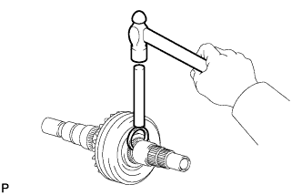
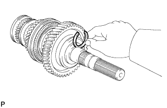
Using a brass bar and hammer, install the snap ring to the output shaft.
-
-
INSTALL 3RD GEAR NEEDLE ROLLER BEARING
-
Coat the 3rd gear needle roller bearing with gear oil, and install it to the 3rd gear.
-
-
INSTALL 3RD GEAR
-
Coat the 3rd gear and No. 3 synchronizer ring set with gear oil, and set them onto the output shaft.
Tech Tips
Align the protrusions of the middle ring of the synchronizer ring set with the notches of the gear.
-
Using SST and a press, install the 3rd gear, No. 3 synchronizer ring set and transmission hub sleeve to the output shaft.
- SST
- 09316-60011 ( 09316-00011 )
Tech Tips
Align the convex portion of the synchronizer ring with the groove of the transmission hub sleeve.
-
Check that the 3rd gear, No. 3 synchronizer ring set, and transmission hub sleeve move smoothly.
-
-
INSTALL NO. 2 CLUTCH HUB SETTING SHAFT SNAP RING
-
Select a new snap ring that will allow minimum clearance.
Standard Clearance 0.1 mm (0.00393 in.) or less Snap Ring Thickness Part No. Thickness Mark 90520-28054 1.90 to 1.95 mm
(0.0748 to 0.0768 in.)
4 90520-28055 1.95 to 2.00 mm
(0.0768 to 0.0787 in.)
5 90520-28056 2.00 to 2.05 mm
(0.0787 to 0.0807 in.)
6 90520-28057 2.05 to 2.10 mm
(0.0807 to 0.0827 in.)
7 90520-28058 2.10 to 2.15 mm
(0.0827 to 0.0847 in.)
8 90520-28059 2.15 to 2.20 mm
(0.0847 to 0.0866 in.)
9 -
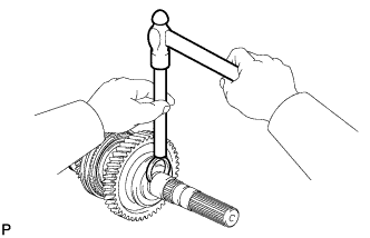
Using a snap ring expander, install the snap ring to the output shaft.
-
-
INSTALL 2ND GEAR NEEDLE ROLLER BEARING
-
Coat the 2nd gear needle roller bearing with gear oil, and install it to the output shaft.
-
-
INSTALL 2ND GEAR
-
Coat the 2nd gear and No. 2 synchronizer ring set with gear oil, then install them to the output shaft.
Tech Tips
Align the protrusions of the middle ring of the synchronizer ring set with the notches of the gear.
-
Using a press, install the 2nd gear, No. 2 synchronizer ring set and transmission hub sleeve to the output shaft.
Tech Tips
Align the convex portion of the synchronizer ring with the groove of the transmission hub sleeve.
-
Check that the 2nd gear, No. 2 synchronizer ring set, and transmission hub sleeve move smoothly.
-
-
INSTALL NO. 1 CLUTCH HUB SHAFT SNAP RING
-
Select a new snap ring that will allow minimum clearance.
Standard Clearance 0.1 mm (0.00393 in.) or less Snap Ring Thickness Part No. Thickness Mark 90520-46004 2.90 to 2.95 mm
(0.114 to 0.116 in.)
A 90520-46005 2.95 to 3.00 mm
(0.116 to 0.118 in.)
B 90520-46006 3.00 to 3.05 mm
(0.118 to 0.120 in.)
C 90520-46007 3.05 to 3.10 mm
(0.120 to 0.122 in.)
D 90520-46008 3.10 to 3.15 mm
(0.122 to 0.124 in.)
E 90520-46009 3.15 to 3.20 mm
(0.124 to 0.126 in.)
F -
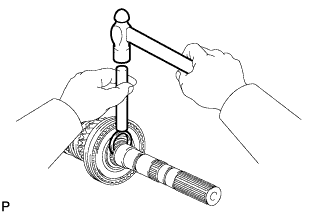
Using a brass bar and a hammer, install the snap ring to the output shaft.
-
-
INSTALL 1ST GEAR NEEDLE ROLLER BEARING
-
Coat the 1st gear needle roller bearing with gear oil, and install it to the output shaft.
-
-
INSTALL 1ST GEAR
-
Coat the 1st gear and No. 1 synchronizer ring set with gear oil, and set them onto the output shaft.
Tech Tips
Align the protrusions of the middle ring of the synchronizer ring set with the notches of the gear.
-
Using SST and press, install the 1st gear, No. 1 synchronizer ring set, and output shaft rear bearing to the output shaft.
- SST
- 09316-60011 ( 09316-00011 )
- 09523-36010
Tech Tips
-
Make sure that the groove of the bearing faces the correct direction as shown in the illustration.
-
Align the convex portion of the synchronizer ring with the groove of the transmission hub sleeve.
-
Check that the transmission hub sleeve, 1st gear and No. 1 synchronizer ring set move smoothly.
-
-
INSTALL REVERSE GEAR SNAP RING
-
Select a new snap ring that will allow minimum clearance.
Standard Clearance 0.1 mm (0.00393 in.) or less Snap Ring Thickness Part No. Thickness Mark 90520-41006 2.40 to 2.45 mm
(0.0945 to 0.0965 in.)
A 90520-41007 2.45 to 2.50 mm
(0.0965 to 0.0984 in.)
B 90520-41008 2.50 to 2.55 mm
(0.0984 to 0.100 in.)
C 90520-41009 2.55 to 2.60 mm
(0.100 to 0.102 in.)
D 90520-41010 2.60 to 2.65 mm
(0.102 to 0.104 in.)
E 90520-41011 2.65 to 2.70 mm
(0.104 to 0.106 in.)
F 90520-41012 2.70 to 2.75 mm
(0.106 to 0.108 in.)
G 90520-41013 2.75 to 2.80 mm
(0.108 to 0.110 in.)
H -
Using a brass bar and a hammer, install the snap ring to the output shaft.
-
-
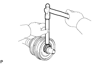
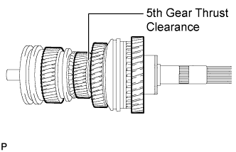
INSPECT 5TH GEAR THRUST CLEARANCE
-
Using a feeler gauge, measure the 5th gear thrust clearance.
Standard Clearance 0.10 to 0.35 mm (0.00394 to 0.0137 in.) If the clearance is outside the specification, replace the defective gear or shaft.
-
-
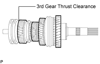
INSPECT 3RD GEAR THRUST CLEARANCE
-
Using a feeler gauge, measure the 3rd gear thrust clearance.
Standard Clearance 0.10 to 0.45 mm (0.00394 to 0.0177 in.) If the clearance is outside the specification, replace the defective gear, transmission clutch hub or shaft.
-
-
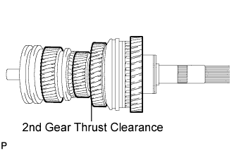
INSPECT 2ND GEAR THRUST CLEARANCE
-
Using a feeler gauge, measure the 2nd gear thrust clearance.
Standard Clearance 0.10 to 0.35 mm (0.00394 to 0.0137 in.) If the clearance is outside the specification, replace the defective gear, transmission clutch hub or shaft.
-
-
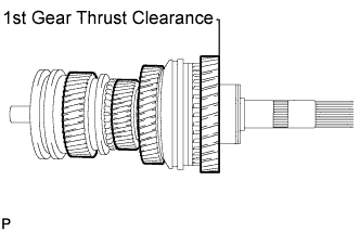
INSPECT 1ST GEAR THRUST CLEARANCE
-
Using a feeler gauge, measure the 1st gear thrust clearance.
Standard Clearance 0.10 to 0.45 mm (0.00394 to 0.0177 in.) If the clearance is outside the specification, replace the defective gear, transmission clutch hub or shaft.
-
-
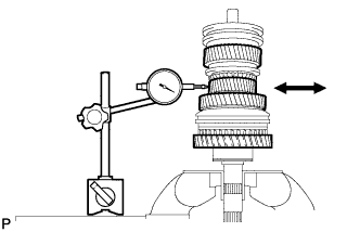
INSPECT 5TH GEAR RADIAL CLEARANCE
-
Using a dial indicator, measure the 5th gear radial clearance.
Standard Clearance 0.015 to 0.068 mm (0.000591 to 0.00267 in.) If the clearance is outside the specification, replace the defective gear, needle roller bearing or shaft.
-
-
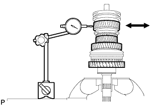
INSPECT 3RD GEAR RADIAL CLEARANCE
-
Using a dial indicator, measure the 3rd gear radial clearance.
Standard Clearance 0.020 to 0.073 mm (0.000788 to 0.00287 in.) If the clearance is outside the specification, replace the defective gear, needle roller bearing or shaft.
-
-
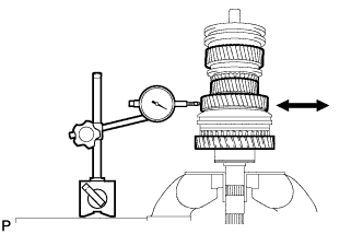
INSPECT 2ND GEAR RADIAL CLEARANCE
-
Using a dial indicator, measure the 2nd gear radial clearance.
Standard Clearance 0.015 to 0.068 mm (0.000591 to 0.00267 in.) If the clearance is outside the specification, replace the defective gear, needle roller bearing or shaft.
-
-
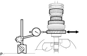
INSPECT 1ST GEAR RADIAL CLEARANCE
-
Using a dial indicator, measure the 1st gear radial clearance.
Standard Clearance 0.020 to 0.073 mm (0.000788 to 0.00287 in.) If the clearance is outside the specification, replace the defective gear, needle roller bearing or shaft.
-