CLUTCH UNIT (for 1GR-FE) INSPECTION

-
INSPECT CLUTCH DISC ASSEMBLY
Note
When replacing the clutch disc assembly, make sure to perform an inspection of the flywheel sub-assembly and clutch cover assembly.
-
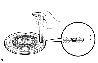
Using a vernier caliper, measure the rivet depth.
Minimum Rivet Depth 0.3 mm (0.0118 in.) If the depth is less than the minimum, replace the clutch disc assembly.
-
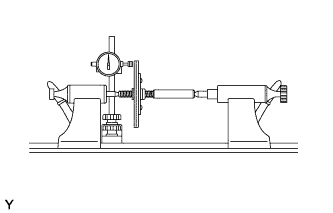
Using a dial indicator with a roller instrument, check the clutch disc runout.
Maximum Runout 0.9 mm (0.0354 in.) If the runout is more than the maximum, replace the clutch disc assembly.
-
-
INSPECT CLUTCH COVER ASSEMBLY
-
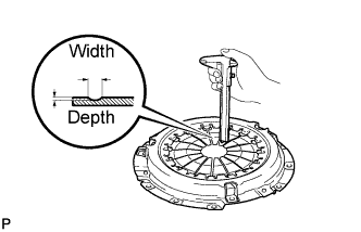
Using a vernier caliper, inspect the depth and width of wear of the diaphragm spring.
Maximum Wear Depth Width 0.6 mm (0.0236 in.) 5.0 mm (0.197 in.) If the wear is more than the maximum, replace the clutch cover assembly.
-
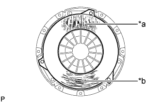
Text in Illustration *1 Hair cracks, scratches or discoloration *2 Hair cracks, discoloration or excessive wear Perform a visual inspection of the clutch cover assembly.
-
Inspect for hair cracks or scratches extending from the center outwards, or discoloration.
-
Inspect for hair cracks in a circular pattern, discoloration or excessive wear.
If there is any damage, replace the clutch cover assembly.
-
-
-
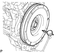
INSPECT FLYWHEEL SUB-ASSEMBLY
-
Using a dial indicator, inspect the flywheel runout.
Maximum Runout 0.1 mm (0.00393 in.) If the runout is more than the maximum, replace the flywheel sub-assembly.
-
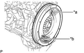
Text in Illustration *1 Hair cracks, scratches or discoloration *2 Hair cracks, discoloration or excessive wear Perform a visual inspection of the flywheel sub-assembly.
-
Inspect for hair cracks or scratches extending from the center outwards, or discoloration.
-
Inspect for hair cracks in a circular pattern, discoloration or excessive wear.
If there is any damage, replace the flywheel sub-assembly.
-
-
-
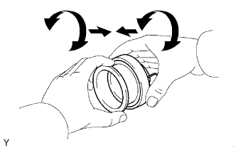
INSPECT CLUTCH RELEASE BEARING ASSEMBLY
-
Check that the clutch release bearing moves smoothly without abnormal resistance by turning the sliding parts of the clutch release bearing (contact surfaces with the clutch cover) while applying force in the axial direction.
-
Inspect the clutch release bearing for damage or wear.
Replace the release bearing assembly as necessary.
-
-
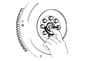
INSPECT INPUT SHAFT BEARING
-
Turn the bearing by hand while applying force in the direction of the rotation.
If the bearing is stuck or difficult to turn, replace the input shaft bearing.
Tech Tips
The bearing is permanently lubricated and requires no cleaning or lubrication.
-
-
REPLACE INPUT SHAFT BEARING
-
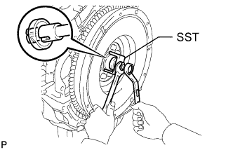
Using SST, remove the bearing.
- SST
- 09303-35011
-
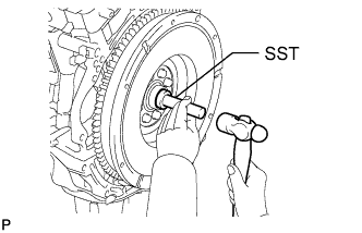
Using SST and a hammer, install a new bearing.
- SST
- 09304-12012
Tech Tips
After installing the input shaft bearing to the engine side, make sure that it rotates smoothly.
-