TRANSFER ASSEMBLY INSPECTION

-
INSPECT TRANSFER INPUT SHAFT
-
Using a micrometer, measure the diameter of the input shaft journal surface.
Minimum Diameter 68 mm (2.68 in.) If the diameter is less than the minimum, replace the input shaft.
-
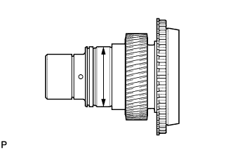
Using a dial indicator, measure the inside diameter of the input shaft bush.
Maximum Inside Diameter 46 mm (1.81 in.) If the inside diameter is more than the maximum, replace the input shaft.
-
-
INSPECT TRANSFER LOW PLANETARY GEAR ASSEMBLY
-
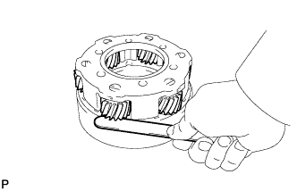
Using a feeler gauge, measure the thrust clearance of the pinion gear.
Standard Clearance 0.11 to 0.85 mm (0.00434 to 0.0334 in.) Maximum Clearance 0.85 mm (0.0334 in.) If the clearance is more than the maximum, replace the low planetary gear assembly.
-
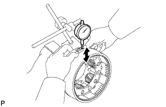
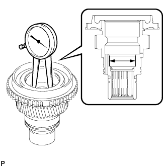
Using a dial indicator, measure the radial clearance of the pinion gear.
Standard Clearance 0.01 to 0.04 mm (0.000434 to 0.00150 in.) Maximum Clearance 0.04 mm (0.00150 in.) If the clearance is more than the maximum, replace the low planetary gear assembly.
-
-
INSPECT REAR TRANSFER OUTPUT SHAFT
-
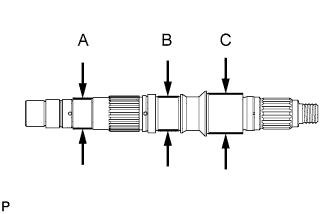
Using a micrometer, measure the diameter of the output shaft journals.
Minimum Diameter Journal Specified Condition A 38 mm (1.50 in.) B 42 mm (1.65 in.) C 49 mm (1.93 in.) If the diameter is less than the minimum, replace the output shaft.
-
-
INSPECT NO. 1 TRANSFER GEAR SHIFT FORK AND FRONT DRIVE CLUTCH SLEEVE
-
Using a feeler gauge, measure the clearance between the clutch sleeve and gear shift fork.
Maximum Clearance 0.8 mm (0.0315 in.) If the clearance is more than the maximum, replace the clutch sleeve or shift fork.
-
-
INSPECT NO. 2 TRANSFER GEAR SHIFT FORK AND HIGH AND LOW CLUTCH SLEEVE
-
Using a feeler gauge, measure the clearance between the clutch sleeve and gear shift fork.
Maximum Clearance 3.15 mm (0.124 in.) If the clearance is more than the maximum, replace the clutch sleeve or shift fork.
-
-
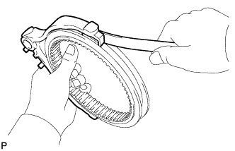
INSPECT NO. 1 SYNCHRONIZER RING (for Manual Transmission)
-
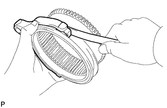
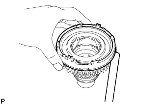
Apply gear oil to the cone of the input shaft, and check that it does not turn in both directions while pushing the No. 1 synchronizer ring.
If it can turn, replace the No. 1 synchronizer ring.
-
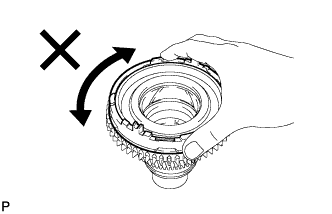
Push the No. 1 synchronizer ring to the cone of the input shaft. Measure the clearance between the No. 1 synchronizer ring and input shaft.
Standard Clearance 0.86 to 1.54 mm (0.0339 to 0.0606 in.) Minimum Clearance 0.86 mm (0.0339 in.) If the clearance is not as specified, replace the No. 1 synchronizer ring with a new one.
-