OIL COOLER INSTALLATION

-
INSTALL OIL COOLER ASSEMBLY
Text in Illustration *a Lower Side *b Outward
-
Connect the oil cooler inlet hose and outlet hose.
-
Install the rear transmission oil cooler air duct with the 4 bolts, and then install the air cooled oil cooler tube to the transmission oil cooler air duct with the bolt.
- Torque:
- 4.9 N*m { 50 kgf*cm, 43 in.*lbf }
-
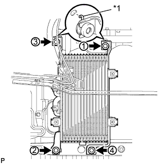
Text in Illustration *1 Claw Temporarily put the oil cooler on the radiator support.
Note
Securely attach the 2 claws of the oil cooler into the holes of the radiator support.
-
Install the 4 bolts in the sequence shown in the illustration.
- Torque:
- 12 N*m { 122 kgf*cm, 9 ft.*lbf }
-
-
INSTALL TRANSMISSION OIL COOLER AIR DUCT
-
Install the oil cooler air duct with the 4 bolts.
- Torque:
- 4.9 N*m { 50 kgf*cm, 43 in.*lbf }
-
-
INSTALL OIL COOLER TUBE
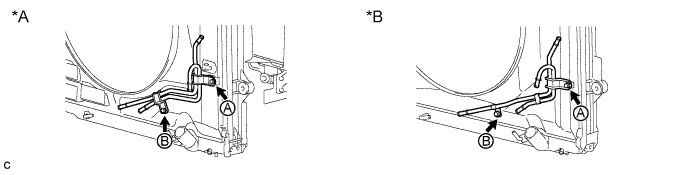
Text in Illustration *A for 1VD-FTV *B for 1UR-FE, 3UR-FE
-
Temporarily install the oil cooler tube to the fan shroud with bolt A. Install bolt B and tighten it to the specified torque. Then tighten bolt A to the specified torque.
- Torque:
- 5.0 N*m { 51 kgf*cm, 44 in.*lbf }
-
-
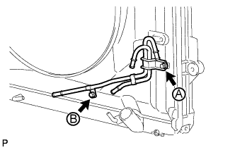
INSTALL OIL COOLER TUBE (w/o Air Cooled Transmission Oil Cooler)
-
Temporarily install the oil cooler tube to the fan shroud with bolt A. Install bolt B and tighten it to the specified torque. Then tighten bolt A to the specified torque.
- Torque:
- 5.0 N*m { 51 kgf*cm, 44 in.*lbf }
-
-
CONNECT INLET NO. 4 OIL COOLER HOSE
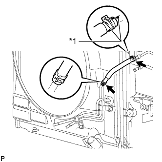
Text in Illustration *1 Paint Mark
-
Connect the inlet oil cooler hose as shown in the illustration.
Note
Make sure the pinching portion of each clip is facing the direction shown in the illustration and the paint marks are aligned as shown in the illustration.
-
-
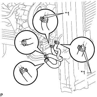
CONNECT INLET NO. 2 OIL COOLER HOSE AND INLET NO. 3 OIL COOLER HOSE
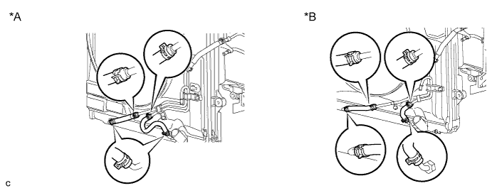
Text in Illustration *A for 1VD-FTV *B for 1UR-FE, 3UR-FE
-
Connect the 2 inlet oil cooler hoses as shown in the illustration.
Note
Make sure the pinching portion of each clip is facing the direction shown in the illustration.
-
-
CONNECT INLET NO. 2 OIL COOLER HOSE AND INLET NO. 3 OIL COOLER HOSE (w/o Air Cooled Transmission Oil Cooler)
-
Connect the 2 inlet oil cooler hoses as shown in the illustration.
Note
Make sure the pinching portion of each clip is facing the direction shown in the illustration.
-
-
CONNECT INLET NO. 1 OIL COOLER HOSE AND OUTLET NO. 1 OIL COOLER HOSE
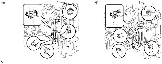
Text in Illustration *A for 1VD-FTV *B for 1UR-FE, 3UR-FE *1 Paint Mark - -
-
Connect the 2 oil cooler hoses as shown in the illustration.
Note
Make sure the pinching portion of each clip is facing the direction shown in the illustration and the paint marks are aligned as shown in the illustration.
-
Attach the hose to the flexible hose clamp and close the clamp as shown in the illustration.
-
-
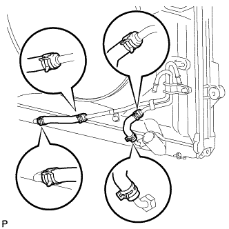
CONNECT INLET NO. 1 OIL COOLER HOSE AND OUTLET NO. 1 OIL COOLER HOSE (w/o Air Cooled Transmission Oil Cooler)
Text in Illustration *1 Paint Mark
-
Connect the 2 oil cooler hoses as shown in the illustration.
Note
Make sure the pinching portion of each clip is facing the direction shown in the illustration and the paint marks are aligned as shown in the illustration.
-
-
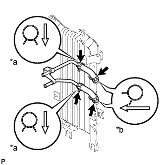
CONNECT TRANSMISSION OIL COOLER HOSE
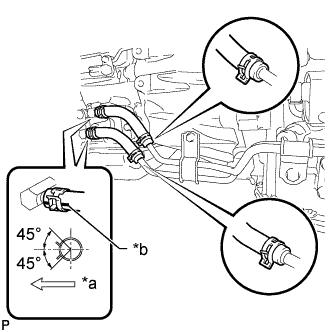
Text in Illustration *a RH Side *b Paint Mark
-
Connect the 2 transmission oil cooler hoses as shown in the illustration.
Note
-
Make sure the pinching portion of each clip is facing the direction shown in the illustration.
-
Make sure the paint mark of each hose is facing outward.
-
-
-
ADD AUTOMATIC TRANSMISSION FLUID
-
Add automatic transmission fluid Click here.
-
-
INSTALL FRONT BUMPER COVER (w/ Air Cooled Transmission Oil Cooler)
-
for Standard:
-
w/ Winch:
-
-
INSTALL NO. 2 ENGINE UNDER COVER
-
Install the No. 2 engine under cover with the 2 bolts.
- Torque:
- 29 N*m { 296 kgf*cm, 21 ft.*lbf }
-
-
INSTALL NO. 1 ENGINE UNDER COVER SUB-ASSEMBLY
-
Install the No. 1 engine under cover sub-assembly with the 10 bolts.
- Torque:
- 29 N*m { 296 kgf*cm, 21 ft.*lbf }
-
-
INSTALL FRONT FENDER APRON TRIM PACKING C
-
Install the front fender apron trim packing C with the 4 clips.
-
-
INSTALL FRONT FENDER APRON TRIM PACKING A
-
Install the front fender apron trim packing A with the 3 clips.
-