PARK / NEUTRAL POSITION SWITCH INSTALLATION

-
INSTALL PARK/NEUTRAL POSITION SWITCH ASSEMBLY
Tech Tips
Make sure that the manual valve lever shaft has not been rotated prior to installing the park/neutral position switch as the detent spring may become detached from the manual valve lever shaft.
-
Clean the bolt and the bolt hole.
-
Apply adhesive to 2 or 3 threads on the end of the bolt.
Adhesive Toyota Genuine Adhesive 1344, Three Bond 1344 or equivalent -
Install the switch to the manual valve shaft.
-
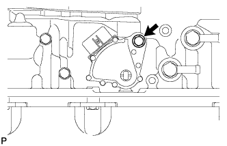
Temporarily install the park/neutral position switch assembly with the bolt.
Tech Tips
Tighten the bolt to the specified torque when adjusting the park/neutral position switch assembly.
-
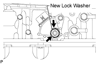
Install a new lock washer and the nut.
- Torque:
- 6.9 N*m { 70 kgf*cm, 61 in.*lbf }
-
Temporarily install the control shaft lever RH.
-
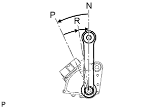
Turn the control shaft lever RH counterclockwise until it stops, and then turn it clockwise 2 notches to set it to the N position.
-
Remove the control shaft lever RH.
-
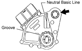
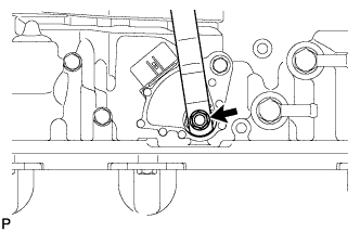
Align the groove with the neutral basic line.
-
Hold the switch in the position described above and tighten the bolt.
- Torque:
- 13 N*m { 133 kgf*cm, 10 ft.*lbf }
-
Using a screwdriver, bend the tabs of the lock washer.
-
Install the transmission control rod bush and collar to the transmission control shaft lever RH.
-
Install the transmission control shaft lever RH with the spring washer and nut.
- Torque:
- 16 N*m { 163 kgf*cm, 12 ft.*lbf }
-
Connect the switch connector.
-
-
CONNECT FLOOR SHIFT GEAR SHIFTING ROD SUB-ASSEMBLY
-
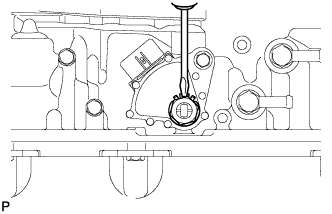
Connect the shifting rod to the transmission control shaft lever RH with the pin.
-
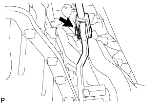
Install a new clip.
-
-
INSPECT SHIFT LEVER POSITION
-
When moving the shift lever from P to R with the ignition switch ON and the brake pedal depressed, make sure that it moves smoothly and correctly into position.
-
Check that the shift lever does not stop when moving the shift lever from R to P, and check that the shift lever does not stick when moving the shift lever from D to S.
-
Start the engine and make sure that the vehicle moves forward after moving the shift lever from N to D and moves rearward after moving the shift lever to R.
If the operation cannot be performed as specified, inspect the park/neutral position switch assembly and check the shift lever assembly installation condition.
-
-
INSPECT PARK/NEUTRAL POSITION SWITCH ASSEMBLY
-
INSTALL FRONT EXHAUST PIPE ASSEMBLY (w/ DPF)
-
Install a new gasket and the front exhaust pipe to the monolithic converter RH with 3 new nuts.
- Torque:
- 48 N*m { 489 kgf*cm, 35 ft.*lbf }
-
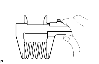
Check the free length.
-
Using a vernier caliper, measure the free length of the compression spring.
Free length 43 mm (1.69 in.) If the free length is less than the minimum, replace the compression spring.
-
-
Install a new gasket and connect the front exhaust pipe assembly with the 2 bolts and 2 compression springs.
- Torque:
- 43 N*m { 438 kgf*cm, 32 ft.*lbf }
-
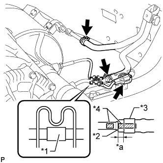
Text in Illustration *1 Tape *2 Stopper *3 Clip *4 Paint Mark *a 2 to 7 mm (0.0787 to 0.276 in.) Attach the clamp and connect the exhaust gas temperature sensor connector.
Tech Tips
Make sure that the tape is in the position shown in the illustration.
-
Install 2 new clips to the 2 air hoses.
-
Connect the 2 air hoses to the front exhaust pipe.
Note
-
Align the paint marks of the front exhaust pipe and air hose and push on the air hose until it contacts the stopper.
-
Make sure the clip is 4 to 10 mm (0.157 to 0.394 in.) from the end of the air hose when installing the clip.
-
Make sure that there is no slack in the air hose, and that it is not twisted or bent.
-
Take care not to damage the inner or outer surface of the air hose when installing it. If the air hose is damaged, replace it with a new one.
-
-
Connect the air fuel ratio sensor connector.
-
-
INSPECT FOR EXHAUST GAS LEAK