CLUTCH MASTER CYLINDER (for LHD) INSTALLATION

-
INSTALL CLUTCH MASTER CYLINDER ASSEMBLY
-
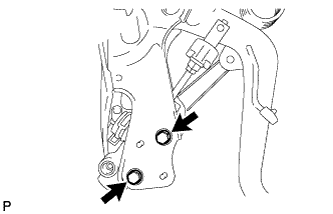
Install the clutch master cylinder with the 2 bolts.
- Torque:
- 12 N*m { 120 kgf*cm, 9 ft.*lbf }
-
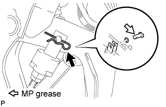
Apply MP grease to the contact surface of the clevis pin and clevis bush.
-
Install the wave washer to the clevis pin.
-
Connect the clevis of the master cylinder to the clutch pedal with the clevis pin.
-
Install a new clip to the clevis pin.
-
-
INSTALL CLUTCH START SWITCH ASSEMBLY
-
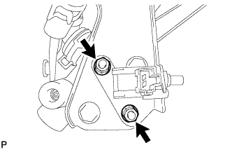
Install the clutch start switch to the clutch pedal bracket, and then temporarily install the 2 nuts.
Tech Tips
The 2 nuts will be tightened to a torque specification in the "Adjust Clutch Start Switch Assembly" procedure.
-
-
INSTALL CLUTCH MASTER CYLINDER TO WAY TUBE
-
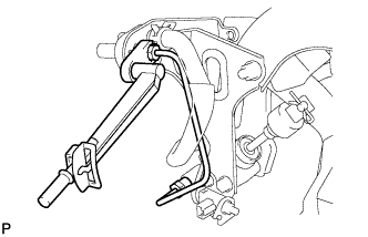
Using a union nut wrench, install the tube to the clutch master cylinder and clutch pedal support way.
- Torque:
- 15 N*m { 155 kgf*cm, 11 ft.*lbf }
Note
Use the formula to calculate special torque values for situations where a union nut wrench is combined with a torque wrench Click here.
-
-
INSTALL CLUTCH RESERVOIR HOSE
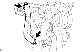
-
Install the clutch reservoir hose to the clutch master cylinder and clutch pedal support way with 2 new clips.
Note
Connect the clutch reservoir hose so that it will not be twisted.
-
-
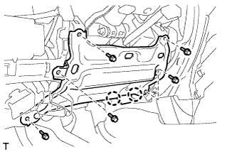
INSTALL CLUTCH PEDAL SUPPORT ASSEMBLY WITH CLUTCH MASTER CYLINDER
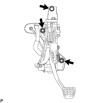
-
Install the clutch pedal support with clutch master cylinder with the bolt and 2 nuts.
- Torque:
- for bolt
- 18 N*m { 184 kgf*cm, 13 ft.*lbf }
- for nut
- 14 N*m { 145 kgf*cm, 10 ft.*lbf }
-
Connect the clutch start switch connector.
-
w/ Cruise Control System:
Connect the clutch switch connector.
-
-
CONNECT CLUTCH MASTER CYLINDER TO FLEXIBLE HOSE TUBE AND CLUTCH RESERVOIR TUBE
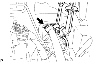
-
Using a union nut wrench, connect the flexible hose tube.
- Torque:
- 15 N*m { 155 kgf*cm, 11 ft.*lbf }
Note
Use the formula to calculate special torque values for situations where a union nut wrench is combined with a torque wrench Click here.
-
Connect the clutch reservoir tube with a new clip.
-
-
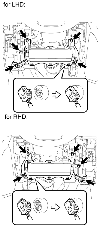
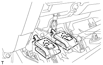
INSTALL MAIN BODY ECU (COWL SIDE JUNCTION BLOCK LH)
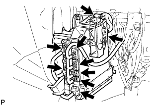
-
Connect the 9 ECU connectors.
-
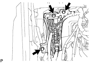
Install the ECU with the 3 bolts.
- Torque:
- 8.0 N*m { 82 kgf*cm, 71 in.*lbf }
-
-
FILL RESERVOIR WITH BRAKE FLUID
-
Fill the reservoir with brake fluid.
Brake Fluid SAE J1703 or FMVSS No. 116 DOT 3
-
-
BLEED CLUTCH LINE
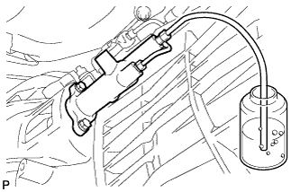
-
Remove the release cylinder bleeder plug cap.
-
Connect a vinyl tube to the bleeder plug.
-
Depress the clutch pedal several times, and then loosen the bleeder plug while the pedal is depressed.
-
When fluid no longer comes out, tighten the bleeder plug, and then release the clutch pedal.
-
Repeat the previous 2 steps until all the air in the fluid is completely bled.
-
Tighten the bleeder plug.
- Torque:
- 11 N*m { 110 kgf*cm, 8 ft.*lbf }
-
Install the bleeder plug cap.
-
Check that all the air has been bled from the clutch line.
-
-
INSPECT AND ADJUST CLUTCH PEDAL SUB-ASSEMBLY
-
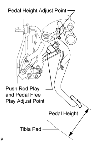
Check that the clutch pedal height is correct.
Standard Clutch Pedal Height from Tibia Pad 162.7 to 172.7 mm (6.41 to 6.79 in.) -
Adjust the clutch pedal height.
-
Loosen the lock nut and turn the stopper bolt or clutch switch until the height is correct. Tighten the lock nut.
- Torque:
- 16 N*m { 160 kgf*cm, 12 ft.*lbf }
-
-
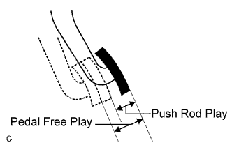
Check that the clutch pedal free play and push rod play are correct.
Tech Tips
Pay close attention to the change in resistance to distinguish between pedal free play and push rod play while performing the inspection.
-
Depress the clutch pedal until the clutch resistance begins to be felt.
Standard Pedal Free Play 5.0 to 15.0 mm (0.197 to 0.591 in.) -
Gently depress the clutch pedal until the resistance begins to increase a little.
Standard Push Rod Play at Pedal Top 1.0 to 5.0 mm (0.0394 to 0.197 in.)
-
-
Adjust the clutch pedal free play and push rod play.
Tech Tips
The push rod play can be adjusted by changing the length of the push rod. Pedal free play changes together with push rod play.
-
Loosen the lock nut and turn the clutch push rod until the clutch pedal free play and push rod play are correct.
Note
If pedal free play and push rod play are not within the standard range even after adjustment, inspect the related parts.
-
Tighten the lock nut.
- Torque:
- 12 N*m { 120 kgf*cm, 9 ft.*lbf }
-
After adjusting the clutch pedal free play and push rod play, check the clutch pedal height.
Standard Clutch Pedal Height from Tibia Pad 162.7 to 172.7 mm (6.41 to 6.79 in.)
-
-
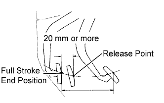
Check the clutch release point.
-
Pull the parking brake lever and chock the wheels.
-
Start the engine and allow it to idle.
-
Without depressing the clutch pedal, slowly move the shift lever to R until the gears engage.
-
Gradually depress the clutch pedal and measure the stroke distance from the point that the gear noise stops (release point) up to the full stroke end position.
Standard Distance from Pedal Stroke End Position to Release Point 20 mm (0.787 in.) or more If the distance is not as specified, perform the following operations:
-
Check the clutch pedal height.
-
Check the push rod play and pedal free play.
-
Bleed the clutch line.
-
Check the clutch cover and disc.
-
-
-
-
ADJUST CLUTCH START SWITCH ASSEMBLY
-
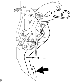
While depressing the clutch pedal, tighten the 2 nuts so that the clearance between the clutch pedal and clutch start switch is within the specification.
Standard clearance between clutch pedal and clutch start switch 4.1 to 6.1 mm (0.162 to 0.240 in.) - Torque:
- 5.0 N*m { 51 kgf*cm, 44 in.*lbf }
-
-
CHECK FLUID LEVEL IN RESERVOIR
-
Check the fluid level.
If the brake fluid level is low, check for leaks and inspect the disc brake pad. If necessary, refill the reservoir with brake fluid after repair or replacement.
Brake fluid SAE J1703 or FMVSS No. 116 DOT 3
-
-
INSPECT FOR CLUTCH FLUID LEAK
-
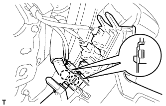
INSTALL LOWER INSTRUMENT PANEL SUB-ASSEMBLY (w/o Driver Side Knee Airbag)
-
Attach the 2 claws and connect the DLC3.
-
Install the lower instrument panel with the 5 bolts.
-
-
INSTALL DRIVER SIDE KNEE AIRBAG ASSEMBLY (w/ Driver Side Knee Airbag)
-
Connect the connector.
Note
When handling the airbag connector, take care not to damage the airbag wire harness.
-
Install the driver side knee airbag with the 5 bolts.
- Torque:
- 10 N*m { 102 kgf*cm, 7 ft.*lbf }
-
-
INSTALL NO. 1 SWITCH HOLE BASE
-
Connect the connectors.
-
Attach the 4 claws to install the No. 1 switch hole base.
-
-
INSTALL LOWER NO. 1 INSTRUMENT PANEL FINISH PANEL
-
Connect the connectors.
-
for Automatic Air Conditioning System:
-
Attach the 2 claws to install the room temperature sensor.
-
-
Attach the 2 claws to connect the 2 control cables.
-
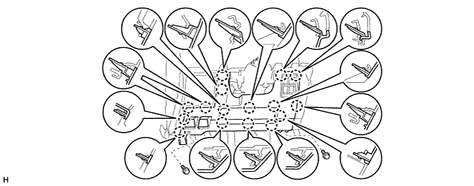
w/ Driver Side Knee Airbag:
-
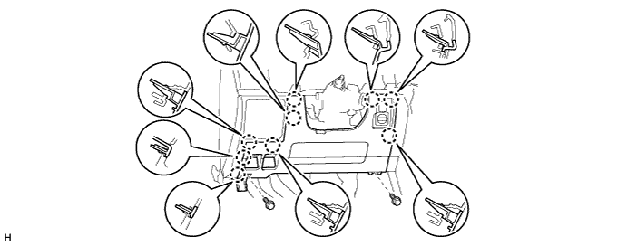
Attach the 16 claws to install the lower No. 1 instrument panel finish panel.
-
Install the 2 bolts.
-
-
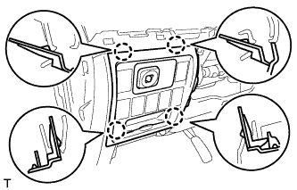
w/o Driver Side Knee Airbag:
-
Attach the 9 claws to install the lower No. 1 instrument panel finish panel.
-
Install the 2 bolts.
-
-
Attach the 2 claws to close the hole cover.
-
-
INSTALL COWL SIDE TRIM BOARD LH

-
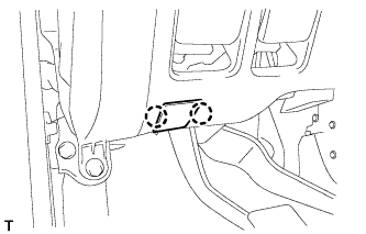
Attach the 2 clips to install the cowl side trim board.
-
Install the cap nut.
-
-
INSTALL NO. 1 INSTRUMENT PANEL UNDER COVER SUB-ASSEMBLY (w/ Floor Under Cover)
-
Connect the connectors.
-
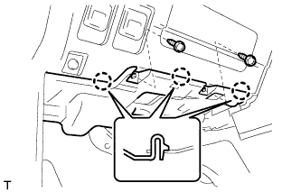
Attach the 3 claws to install the No. 1 instrument panel under cover.
-
Install the 2 screws.
-
-
INSTALL FRONT DOOR SCUFF PLATE LH
Tech Tips
Use the same procedures described for the LH side.
-
INSTALL NO. 2 INSTRUMENT CLUSTER FINISH PANEL GARNISH
-
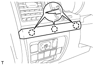
Attach the 2 claws to install the No. 2 instrument cluster finish panel garnish.
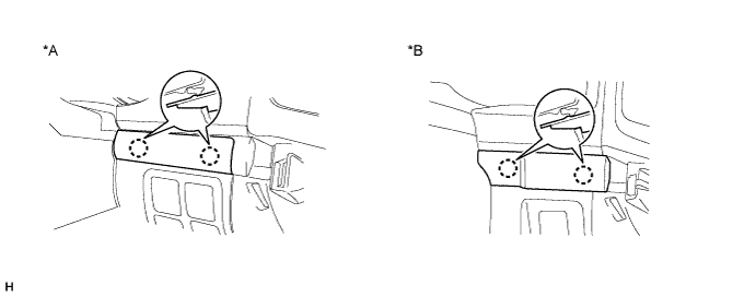
Text in Illustration *A w/ Entry and Start System *B w/o Entry and Start System
-
-
INSTALL NO. 1 INSTRUMENT CLUSTER FINISH PANEL GARNISH
-
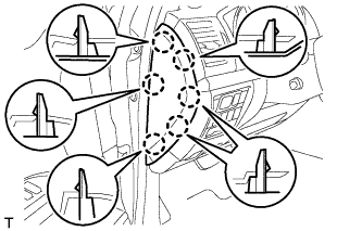
Attach the 3 claws to install the No. 1 instrument cluster finish panel garnish.
-
-
INSTALL INSTRUMENT SIDE PANEL LH
-
Attach the 6 claws to install the instrument side panel.
-
-
INSTALL LOWER INSTRUMENT PANEL PAD SUB-ASSEMBLY LH
-
Connect the connectors and attach the 2 clamps.
-
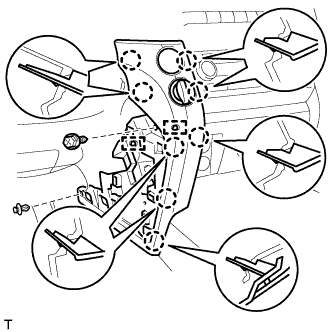
Attach the 8 claws to install the lower instrument panel pad sub-assembly.
-
Install the clip and screw.
-
-
INSTALL NO. 2 INSTRUMENT PANEL FINISH PANEL CUSHION
-
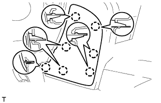
Attach the 7 claws to install the No. 2 instrument panel finish panel cushion.
-