AUTOMATIC TRANSMISSION SYSTEM (for 3UR-FE) L4 Position Switch Circuit
DESCRIPTION
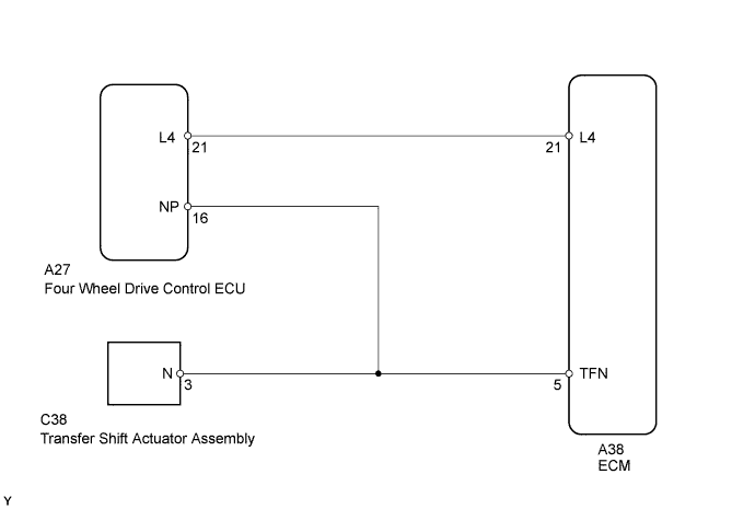
The four wheel drive control ECU judges whether the transfer is in L4 based on the information from the limit switch inside the transfer shift actuator assembly which is detected by the ECM. The four wheel drive control ECU inputs a signal to the combination meter assembly via CAN communication and turns on the 4LO indicator when the transfer is in L4.
WIRING DIAGRAM
INSPECTION PROCEDURE
PROCEDURE
-
CHECK HARNESS AND CONNECTOR (FOUR WHEEL DRIVE CONTROL ECU - BODY GROUND)
-
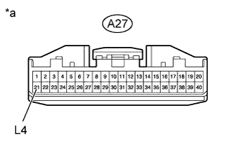
Text in Illustration *a Front view of wire harness connector
(to Four Wheel Drive control ECU)
Disconnect the four wheel drive control ECU connector.
-
Measure the resistance according to the value(s) in the table below.
Standard Resistance Tester Connection Condition Specified Condition A27-21 (L4) - Body ground Always 10 kΩ or higher
NG 
CHECK HARNESS AND CONNECTOR (FOUR WHEEL DRIVE CONTROL ECU - ECM) Click here
OK 
GO TO TRANSFER SYSTEM (INSPECTION) Click here
-
-
CHECK HARNESS AND CONNECTOR (FOUR WHEEL DRIVE CONTROL ECU - ECM)
-
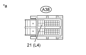
Text in Illustration *a Front view of wire harness connector
(to ECM)
Disconnect the A38 ECM connector.
-
Disconnect the four wheel drive control ECU connector.
-
Measure the resistance according to the value(s) in the table below.
Standard Resistance Tester Connection Condition Specified Condition A38-21 (L4) - Body ground Always 10 kΩ or higher
NG 
REPAIR OR REPLACE HARNESS OR CONNECTOR
OK
REPLACE ECM Click here
-