AUTOMATIC TRANSMISSION UNIT INSPECTION

-
INSPECT AUTOMATIC TRANSMISSION OIL PAN SUB-ASSEMBLY
-
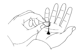
Remove the magnets, and use them to collect steel particles.
-
Carefully look at the foreign matter and particles in the pan and on the magnets to anticipate the type of wear you will find in the transmission.
-
Steel (magnetic): bearing, gear and clutch plate wear
-
Brass (non-magnetic): bushing wear
-
-
-
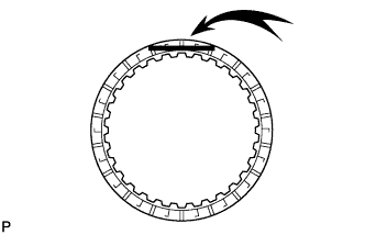
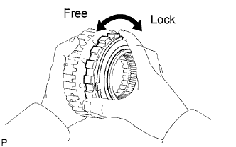
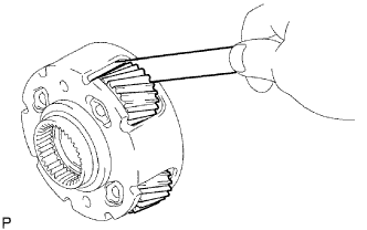
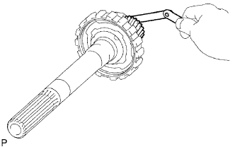
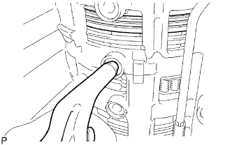
INSPECT NO. 2 1-WAY CLUTCH ASSEMBLY
-
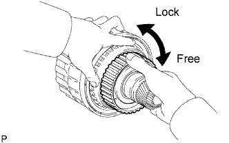
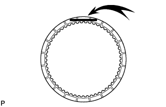
Hold the reverse clutch hub and turn the 1-way clutch assembly.
-
Check that the 1-way clutch turns freely clockwise and locks when turned counterclockwise.
-
-
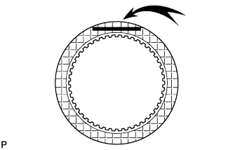
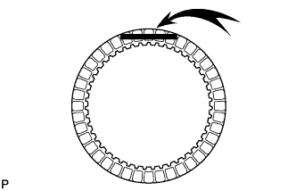
INSPECT REAR CLUTCH DISC
-

Replace all discs if one of the following problems is present: 1) a disc, plate or flange is worn or burnt, 2) the lining of a disc is peeled off or discolored, or 3) the grooves or printed numbers have even a little bit of damage.
Note
Before assembling new discs, soak them in ATF for at least 15 minutes.
-
-
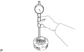
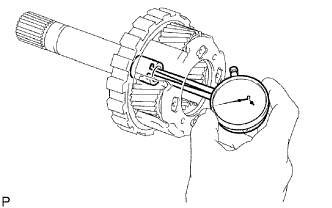
INSPECT REVERSE CLUTCH HUB SUB-ASSEMBLY
-
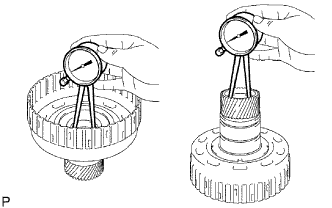
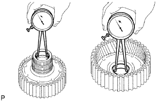
Using a dial indicator, measure the inside diameter of the reverse clutch hub bush.
Standard inside diameter 35.812 to 35.837 mm (1.410 to 1.411 in.) Maximum inside diameter 35.887 mm (1.413 in.)
-
If the inside diameter is more than the maximum, replace the reverse clutch hub.
-
-
-
INSPECT FORWARD CLUTCH HUB SUB-ASSEMBLY
-
Using a dial indicator, measure the inside diameter of the forward clutch hub bush.
Standard inside diameter 26.037 to 26.062 mm (1.025 to 1.026 in.) Maximum inside diameter 26.112 mm (1.028 in.)
-
If the inside diameter is more than the maximum, replace the forward clutch hub.
-
-
-
INSPECT FORWARD MULTIPLE DISC CLUTCH DISC
-
Replace all discs if one of the following problems is present: 1) a disc, plate or flange is worn or burnt, 2) the lining of a disc is peeled off or discolored, or 3) the grooves or printed numbers have even a little bit of damage.
Note
Before assembling new discs, soak them in ATF for at least 15 minutes.
-
-
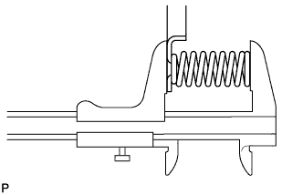
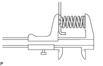
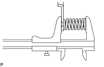
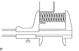
INSPECT FORWARD CLUTCH RETURN SPRING SUB-ASSEMBLY
-
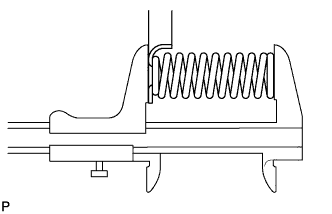
Using a vernier caliper, measure the free length of the spring together with the spring seat.
Standard free length 26.74 mm (1.05 in.)
-
-
INSPECT DIRECT CLUTCH DISC
-
Replace all discs if one of the following problems is present: 1) a disc, plate or flange is worn or burnt, 2) the lining of a disc is peeled off or discolored, or 3) the grooves or printed numbers have even a little bit of damage.
Note
Before assembling new discs, soak them in ATF for at least 15 minutes.
-
-
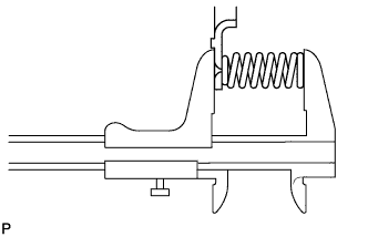
INSPECT REVERSE CLUTCH RETURN SPRING SUB-ASSEMBLY
-
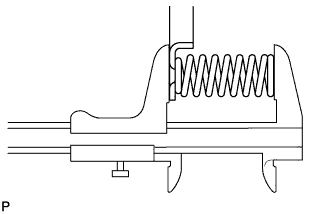
Using a vernier caliper, measure the free length of the spring together with the spring seat.
Standard free length 21.04 mm (0.828 in.)
-
-
INSPECT DIRECT CLUTCH RETURN SPRING SUB-ASSEMBLY
-
Using a vernier caliper, measure the free length of the spring together with the spring seat.
Standard free length 19.51 mm (0.768 in.)
-
-
INSPECT NO. 3 BRAKE DISC
-
Replace all discs if one of the following problems is present: 1) a disc, plate or flange is worn or burnt, 2) the lining of a disc is peeled off or discolored, or 3) the grooves or printed numbers have even a little bit of damage.
Note
Before assembling new discs, soak them in ATF for at least 15 minutes.
-
-
INSPECT NO. 3 BRAKE PISTON RETURN SPRING SUB-ASSEMBLY
-
Using a vernier caliper, measure the free length of the spring together with the spring seat.
Standard free length 15.72 mm (0.619 in.)
-
-
INSPECT FRONT PLANETARY GEAR ASSEMBLY
-
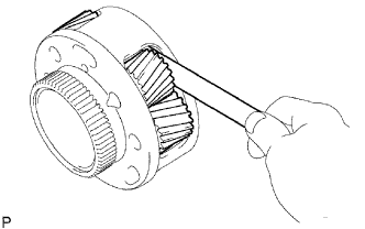
Using a feeler gauge, measure the front planetary pinion gear thrust clearance.
Standard clearance 0.2 to 0.6 mm (0.00787 to 0.0236 in.) Maximum clearance 0.65 mm (0.0256 in.)
-
If the clearance is more than the maximum, replace the front planetary gear assembly.
-
-
Using a cylinder gauge, measure the inside diameter of the front planetary gear bush.
Maximum inside diameter 57.48 mm (2.26 in.)
-
If the inside diameter is more than the maximum, replace the front planetary gear.
-
-
-
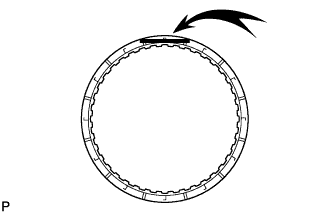
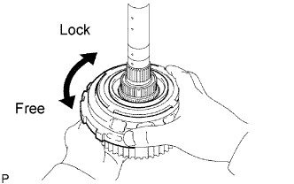
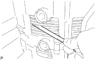
INSPECT 1-WAY CLUTCH ASSEMBLY
-
Install the 1-way clutch to the 1-way clutch inner race.
-
Hold the 1-way clutch inner race and turn the 1-way clutch assembly. Check that the 1-way clutch turns freely counterclockwise and locks when turned clockwise.
-
Remove the 1-way clutch from the 1-way clutch inner race.
-
-
INSPECT NO. 1 BRAKE DISC
-
Replace all discs if one of the following problems is present: 1) a disc, plate or flange is worn or burnt, 2) the lining of a disc is peeled off or discolored, or 3) the grooves or printed numbers have even a little bit of damage.
Note
Before assembling new discs, soak them in ATF for at least 15 minutes.
-
-
INSPECT BRAKE PISTON RETURN SPRING SUB-ASSEMBLY
-
Using a vernier caliper, measure the free length of the spring together with the spring seat.
Standard free length 17.05 mm (0.671 in.)
-
-
INSPECT NO. 2 BRAKE DISC
-
Replace all discs if one of the following problems is present: 1) a disc, plate or flange is worn or burnt, 2) the lining of a disc is peeled off or discolored, or 3) the grooves or printed numbers have even a little bit of damage.
Note
Before assembling new discs, soak them in ATF for at least 15 minutes.
-
-
INSPECT NO. 2 BRAKE PISTON RETURN SPRING SUB-ASSEMBLY
-
Using a vernier caliper, measure the free length of the spring together with the spring seat.
Standard free length 17.45 mm (0.687 in.)
-
-
INSPECT CENTER PLANETARY GEAR ASSEMBLY
-
Using a feeler gauge, measure the center planetary pinion gear thrust clearance.
Standard clearance 0.12 to 0.68 mm (0.00472 to 0.0268 in.) Maximum clearance 0.73 mm (0.0287 in.)
-
If the clearance is more than the maximum, replace the center planetary gear assembly.
-
-
-
INSPECT NO. 3 1-WAY CLUTCH ASSEMBLY
-
Hold the rear planetary ring gear flange and turn the 1-way clutch. Check that the 1-way clutch turns freely counterclockwise and locks when turned clockwise.
-
-
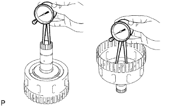
INSPECT REAR PLANETARY RING GEAR FLANGE SUB-ASSEMBLY
-
Using a dial indicator, measure the inside diameter of the rear planetary ring gear bush.
Standard inside diameter 32.176 to 32.201 (1.267 to 1.268 in.) Maximum inside diameter 32.251 mm (1.270 in.)
-
If the inside diameter is more than the maximum, replace the rear planetary ring gear.
-
-
-
INSPECT INTERMEDIATE SHAFT
-
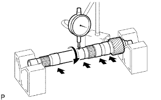
Using a dial indicator, measure the intermediate shaft runout.
Standard runout 0.03 mm (0.00118 in.) Maximum runout 0.08 mm (0.00315 in.) If the runout is more than the maximum, replace the intermediate shaft with a new one.
-
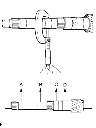
Using a micrometer, measure the diameter of the intermediate shaft at the positions shown in the diagram.
Standard diameter A, B 25.962 to 25.975 mm (1.022 to 1.023 in.) C, D 32.062 to 32.075 mm (1.262 to 1.263 in.) Minimum diameter A, B 25.912 mm (1.02 in.) C, D 32.012 mm (1.26 in.) If the diameter is less than the minimum, replace the intermediate shaft with a new one.
-
-
INSPECT NO. 4 BRAKE DISC
-
Replace all discs if one of the following problems is present: 1) a disc, plate or flange is worn or burnt, 2) the lining of a disc is peeled off or discolored, or 3) the grooves or printed numbers have even a little bit of damage.
Note
Before assembling new discs, soak them in ATF for at least 15 minutes.
-
-
INSPECT REAR PLANETARY GEAR ASSEMBLY
-
Using a feeler gauge, measure the rear planetary pinion gear thrust clearance.
Standard clearance 0.2 to 0.6 mm (0.00787 to 0.0236 in.) Maximum clearance 0.65 mm (0.0256 in.)
-
If the clearance is more than the maximum, replace the planetary gear assembly.
-
-
Using a dial indicator, measure the inside diameter of the rear planetary gear bush.
Maximum inside diameter 20.075 mm (0.790 in.)
-
If the inside diameter is more than the maximum, replace the rear planetary gear assembly.
-
-
-
INSPECT 1ST AND REVERSE BRAKE RETURN SPRING SUB-ASSEMBLY
-
Using a vernier caliper, measure the free length of the spring together with the spring seat.
Standard free length 23.74 mm (0.935 in.)
-
-
INSPECT PACK CLEARANCE OF 1ST AND REVERSE BRAKE
-
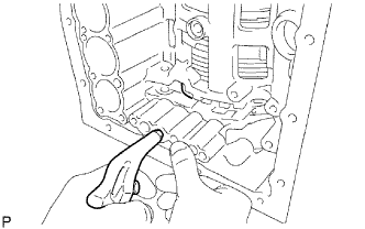
Make sure the 1st and reverse brake piston moves smoothly when applying and releasing compressed air into the transmission case.
-
-
INSPECT PISTON STROKE OF NO. 1 BRAKE PISTON
-
Make sure the No. 1 brake piston moves smoothly when applying and releasing compressed air into the transmission case.
-
Using a feeler gauge, measure the B3 bearing pack clearance between the snap ring and flange.
Standard piston stroke 0.42 to 0.72 mm (0.0165 to 0.0283 in.) If the piston stroke is outside the specification, parts may have been assembled incorrectly. Perform the reassembly again. If the piston stroke is still outside the specification, select another flange.
Tech Tips
There are 4 different thicknesses for the flange.
-
-
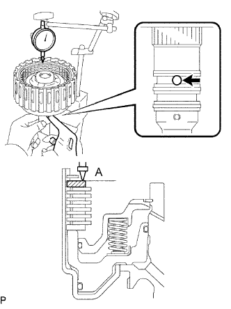
INSPECT PACK CLEARANCE OF DIRECT CLUTCH
-
Using a dial indicator, measure the moving distance (distance A) of the clutch flange at both ends across a diameter while applying air to the oil hole as shown in the illustration, and calculate the average.
Standard pack clearance 0.5 to 0.8 mm (0.0197 to 0.0315 in.) Note
When measuring the moving distance, install a standard flange (thickness: 3.4 mm (0.134 in.)) to the position of the shaded area in the illustration.
Tech Tips
Flange moving distance A = 0.26 to 1.14 mm (0.0102 to 0.0449 in.)
Pack clearance = Flange moving distance A - 0.05 mm (0.00197 in.)
If the pack clearance is outside the standard, select and install a clutch flange that makes the pack clearance within the standard.
Flange Thickness Mark Thickness 2 2.95 to 3.05 mm (0.116 to 0.120 in.) 3 3.05 to 3.15 mm (0.120 to 0.124 in.) 4 3.15 to 3.25 mm (0.124 to 0.128 in.) 5 3.25 to 3.35 mm (0.128 to 0.132 in.) 6 3.35 to 3.45 mm (0.132 to 0.136 in.) 7 3.45 to 3.55 mm (0.136 to 0.140 in.) 8 3.55 to 3.65 mm (0.140 to 0.144 in.) 9 3.65 to 3.75 mm (0.144 to 0.148 in.) A 3.75 to 3.85 mm (0.148 to 0.152 in.)
-
-
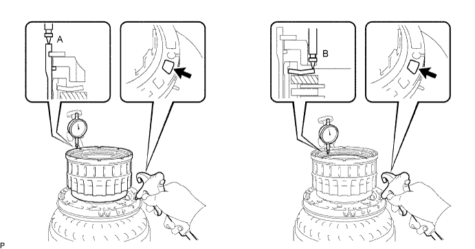
INSPECT PACK CLEARANCE OF REVERSE CLUTCH
-
Using a dial indicator, measure the reverse clutch piston stroke (distance A) and the moving distance (distance B) of the reverse flange at both ends across a diameter while applying air (392 kPa (4.0 kgf/cm2, 57 psi)) to the oil hole as shown in the illustration, and calculate the average.
Standard pack clearance 0.5 to 0.8 mm (0.0197 to 0.0315 in.) Note
When measuring the moving distance, install a standard flange (thickness: 3.3 mm (0.130 in.)) to the position of the shaded area in the illustration.
Tech Tips
Piston stroke A = 1.05 to 2.15 mm (0.0413 to 0.0846 in.)
Flange moving distance B = 0.72 to 1.08 mm (0.0283 to 0.0425 in.)
Pack clearance = Piston stroke A - Flange moving distance B - 0.06 mm (0.00236 in.)
If the pack clearance is outside the standard, select and install a clutch flange that makes the pack clearance within the standard.
Flange Thickness Mark Thickness 0 2.75 to 2.85 mm (0.108 to 0.112 in.) 1 2.85 to 2.95 mm (0.112 to 0.116 in.) 2 2.95 to 3.05 mm (0.116 to 0.120 in.) 3 3.05 to 3.15 mm (0.120 to 0.124 in.) 4 3.15 to 3.25 mm (0.124 to 0.128 in.) 5 3.25 to 3.35 mm (0.128 to 0.132 in.) 6 3.35 to 3.45 mm (0.132 to 0.136 in.) 7 3.45 to 3.55 mm (0.136 to 0.140 in.) 8 3.55 to 3.65 mm (0.140 to 0.144 in.) 9 3.65 to 3.75 mm (0.144 to 0.148 in.) A 3.75 to 3.85 mm (0.148 to 0.152 in.)
-
-
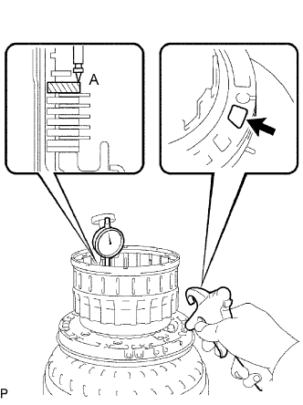
INSPECT PACK CLEARANCE OF FORWARD CLUTCH
-
Using a dial indicator, measure the moving distance (distance A) of the clutch flange at both ends across a diameter while applying air to the oil hole as shown in the illustration, and calculate the average.
Standard pack clearance 0.6 to 0.9 mm (0.0236 to 0.0354 in.) Note
When measuring the moving distance, install a standard flange (thickness: 3.4 mm (0.134 in.)) to the position of the shaded area in the illustration.
Tech Tips
Flange moving distance A = 0.26 to 1.36 mm (0.0102 to 0.0535 in.)
Pack clearance = Flange moving distance A - 0.01 mm (0.000394 in.)
If the pack clearance is outside the standard, select and install a clutch flange that makes the pack clearance within the standard.
Flange Thickness Mark Thickness 0 2.95 to 3.05 mm (0.116 to 0.120 in.) 1 3.05 to 3.15 mm (0.120 to 0.124 in.) 2 3.15 to 3.25 mm (0.124 to 0.128 in.) 3 3.25 to 3.35 mm (0.128 to 0.132 in.) 4 3.35 to 3.45 mm (0.132 to 0.136 in.) 5 3.45 to 3.55 mm (0.136 to 0.140 in.) 6 3.55 to 3.65 mm (0.140 to 0.144 in.) 7 3.65 to 3.75 mm (0.144 to 0.148 in.) 8 3.75 to 3.85 mm (0.148 to 0.152 in.) 9 3.85 to 3.95 mm (0.148 to 0.152 in.) A 3.95 to 4.05 mm (0.152 to 0.159 in.)
-
-
INSPECT INDIVIDUAL PISTON OPERATION
-
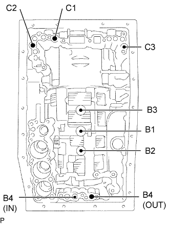
Check the operating sound while applying compressed air into the oil holes indicated in the illustration.
Tech Tips
When inspecting the O/D direct clutch, check with the accumulator piston holes indicated in the illustration.
If there is no sound, disassemble and check the installation condition of the parts.
-
No. 2 clutch (C2)
-
No. 3 clutch (C3)
-
No. 1 clutch (C1)
-
No. 3 brake (B3)
-
No. 1 brake (B1)
-
No. 2 brake (B2)
-
No. 4 brake (B4)
-
-