DYNAMIC RADAR CRUISE CONTROL SYSTEM Distance Control ECU Power Source Circuit
DESCRIPTION
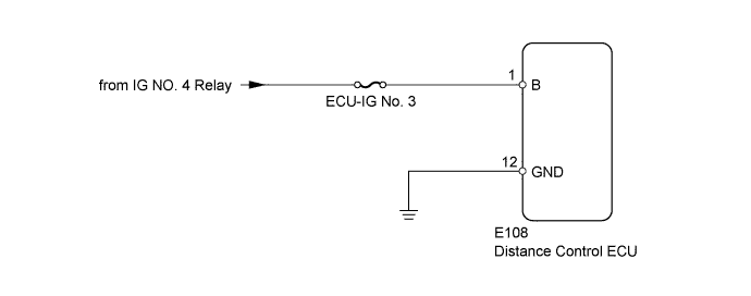
This circuit provides power to operate the distance control ECU.
WIRING DIAGRAM
INSPECTION PROCEDURE
PROCEDURE
-
INSPECT FUSE (ECU-IG No. 3)
-
Remove the ECU-IG No. 3 fuse from the cowl side junction block RH.
-
Measure the resistance according to the value(s) in the table below.
Standard Resistance Tester Connection Condition Specified Condition ECU-IG No. 3 fuse Always Below 1 Ω
NG 
REPLACE FUSE
OK 
-
-
CHECK HARNESS AND CONNECTOR (DISTANCE CONTROL ECU - BATTERY AND BODY GROUND)
-
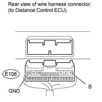
Disconnect the E108 distance control ECU connector.
-
Measure the voltage according to the value(s) in the table below.
Standard Voltage Tester Connection Switch Condition Specified Condition E108-1 (B) - Body ground Engine switch on (IG) 11 to 14 V Engine switch off Below 1 V -
Measure the resistance according to the value(s) in the table below.
Standard Resistance Tester Connection Condition Specified Condition E108-12 (GND) - Body ground Always Below 1 Ω
NG
REPAIR OR REPLACE HARNESS OR CONNECTOR
OK 
PROCEED TO NEXT CIRCUIT INSPECTION SHOWN IN PROBLEM SYMPTOMS TABLE Click here
-