CRUISE CONTROL SYSTEM Clutch Switch Circuit
DESCRIPTION
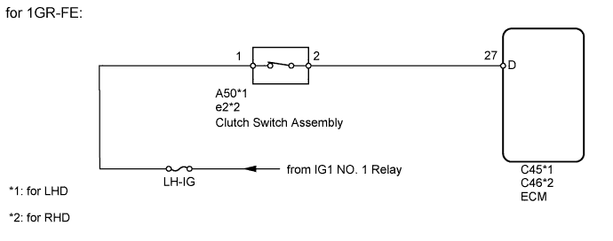
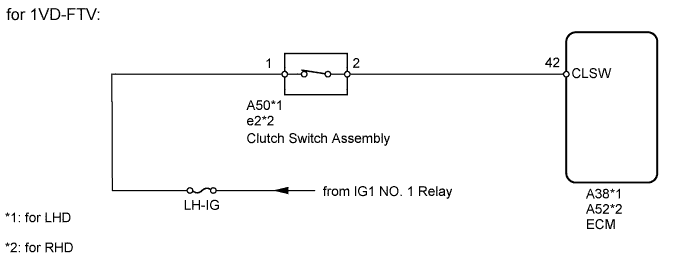
When the clutch pedal is released, the ECM receives positive (+) battery voltage through the LH-IG fuse. While depressing the clutch pedal, the clutch switch sends a signal to terminal D*1 or CLSW*2 of the ECM. The ECM cancels cruise control when terminal D*1 or CLSW*2 receives the signal.
Tech Tips
-
*1: for 1GR-FE
-
*2: for 1VD-FTV
WIRING DIAGRAM
INSPECTION PROCEDURE
PROCEDURE
-
INSPECT FUSE (LH-IG)
-
Remove the LH-IG fuse from the main body ECU.
-
Measure the resistance according to the value(s) in the table below.
Standard Resistance Tester Connection Condition Specified Condition LH-IG fuse Always Below 1 Ω
NG 
REPLACE FUSE
OK 
-
-
CHECK HARNESS AND CONNECTOR (ECM - BATTERY)
-
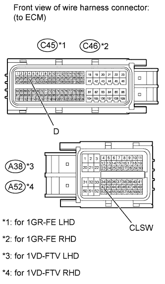
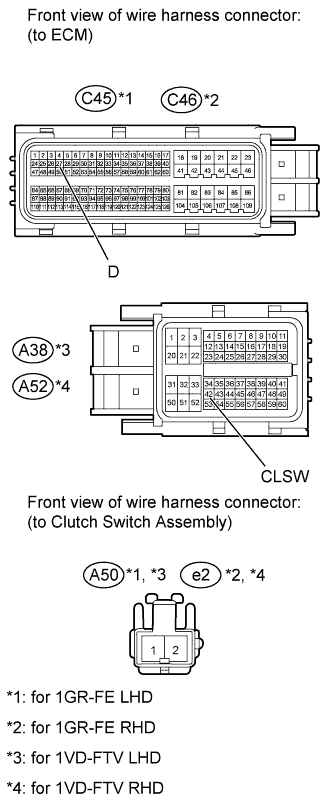
Disconnect the C45*1, C46*2, A38*3 or A52*4 ECM connector.
Tech Tips
-
*1: for 1GR-FE LHD
-
*2: for 1GR-FE RHD
-
*3: for 1VD-FTV LHD
-
*4: for 1VD-FTV RHD
-
-
Measure the voltage according to the value(s) in the table below.
Standard Voltage for 1GR-FE LHD Tester Connection Switch Condition Specified Condition C45-27 (D) - Body ground Ignition switch ON
Clutch pedal depressed
Below 1 V Ignition switch ON
Clutch pedal released
11 to 14 V for 1GR-FE RHD Tester Connection Switch Condition Specified Condition C46-27 (D) - Body ground Ignition switch ON
Clutch pedal depressed
Below 1 V Ignition switch ON
Clutch pedal released
11 to 14 V for 1VD-FTV LHD Tester Connection Switch Condition Specified Condition A38-42 (CLSW) - Body ground Ignition switch ON
Clutch pedal depressed
Below 1 V Ignition switch ON
Clutch pedal released
11 to 14 V for 1VD-FTV RHD Tester Connection Switch Condition Specified Condition A52-42 (CLSW) - Body ground Ignition switch ON
Clutch pedal depressed
Below 1 V Ignition switch ON
Clutch pedal released
11 to 14 V
NG 
INSPECT CLUTCH SWITCH ASSEMBLY Click here
OK 
PROCEED TO NEXT CIRCUIT INSPECTION SHOWN IN PROBLEM SYMPTOMS TABLE Click here
-
-
INSPECT CLUTCH SWITCH ASSEMBLY
-
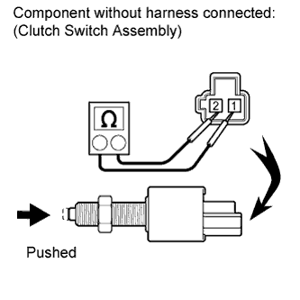
Turn the ignition switch off.
-
Remove the clutch switch assembly Click here for LHD, Click here for RHD).
-
Measure the resistance according to the value(s) in the table below.
Standard Resistance Tester Connection Switch Condition Specified Condition 1 - 2 Pushed (On) Below 1 Ω Not pushed (Off) 10 kΩ or higher Result Result Proceed to OK A NG (for LHD) B NG (for RHD) C -
Install the clutch switch assembly Click here for LHD, Click here for RHD).
B
REPLACE CLUTCH SWITCH ASSEMBLY Click here
C
REPLACE CLUTCH SWITCH ASSEMBLY Click here
A
-
-
CHECK HARNESS AND CONNECTOR (ECM - CLUTCH SWITCH ASSEMBLY)
-
Disconnect the C45*1, C46*2, A38*3 or A52*4 ECM connector.
Tech Tips
-
*1: for 1GR-FE LHD
-
*2: for 1GR-FE RHD
-
*3: for 1VD-FTV LHD
-
*4: for 1VD-FTV RHD
-
-
Disconnect the A50*1 or e2*2 clutch switch assembly connector.
Tech Tips
-
*1: for LHD
-
*2: for RHD
-
-
Measure the resistance according to the value(s) in the table below.
Standard Resistance for 1GR-FE LHD Tester Connection Condition Specified Condition C45-27 (D) - A50-2 Always Below 1 Ω C45-27 (D) - Body ground Always 10 kΩ or higher for 1GR-FE RHD Tester Connection Condition Specified Condition C46-27 (D) - e2-2 Always Below 1 Ω C46-27 (D) - Body ground Always 10 kΩ or higher for 1VD-FTV LHD Tester Connection Condition Specified Condition A38-42 (CLSW) - A50-2 Always Below 1 Ω A38-42 (CLSW) - Body ground Always 10 kΩ or higher for 1VD-FTV RHD Tester Connection Condition Specified Condition A52-42 (CLSW) - e2-2 Always Below 1 Ω A52-42 (CLSW) - Body ground Always 10 kΩ or higher
NG
REPAIR OR REPLACE HARNESS OR CONNECTOR (ECM - CLUTCH SWITCH ASSEMBLY)
OK
REPAIR OR REPLACE HARNESS OR CONNECTOR (BATTERY - CLUTCH SWITCH ASSEMBLY)
-