THERMOSTAT INSTALLATION

-
INSTALL THERMOSTAT
-
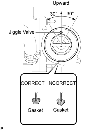
Install a new gasket to the thermostat.
Note
When installing the gasket to the thermostat, be careful not to deform the gasket. Make sure that the groove of the gasket is properly installed onto the thermostat, as shown in the illustration.
-
Insert the thermostat into the water pump with the jiggle valve facing straight upward.
Tech Tips
The jiggle valve may be set within 30° of either side of the prescribed position.
-
-
INSTALL WATER INLET
-
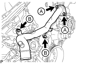
Install the water inlet with the 4 bolts.
- Torque:
- for bolt A
- 21 N*m { 214 kgf*cm, 15 ft.*lbf }
- for bolt B
- 25 N*m { 250 kgf*cm, 18 ft.*lbf }
-
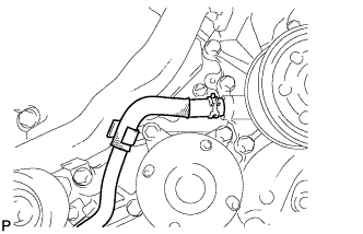
Connect the No. 2 oil cooler hose to the clamp and water pump.
-
-
INSTALL NO. 1 IDLER PULLEY BRACKET (w/ Viscous Heater)
-
Install the No. 1 idler pulley bracket with the bolt.
- Torque:
- 49 N*m { 495 kgf*cm, 36 ft.*lbf }
-
-
INSTALL VISCOUS WITH MAGNET CLUTCH HEATER ASSEMBLY (w/ Viscous Heater)
-
Install the heater assembly with the 2 bolts.
- Torque:
- 48.5 N*m { 495 kgf*cm, 36 ft.*lbf }
-
Connect the 2 heater hoses.
-
Using pliers, grip the claws of the clips and slide the 2 clips.
-
Connect the connector and attach the clamp.
-
-
INSTALL HEATER WATER PIPE SUB-ASSEMBLY (w/ Viscous Heater)
-
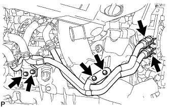
Connect the heater water pipe to the viscous heater with magnet clutch, and install the 4 bolts.
- Torque:
- 9.8 N*m { 100 kgf*cm, 87 in.*lbf }
-
-
INSTALL FAN PULLEY
-
INSTALL FAN SHROUD WITH FAN
-
Install the shroud together with the fluid coupling fan between the radiator and engine components.
Note
Be careful not to damage the radiator core.
-
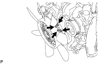
Temporarily install the fluid coupling fan to the fan bracket with the 4 nuts.
Tech Tips
Tighten the nuts as much as possible by hand.
-
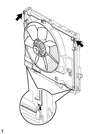
Attach the shroud claws to the radiator.
-
Install the shroud with the 2 bolts.
- Torque:
- 8.0 N*m { 82 kgf*cm, 71 in.*lbf }
-
Tighten the 4 nuts of the fluid coupling fan.
- Torque:
- 21 N*m { 214 kgf*cm, 15 ft.*lbf }
-
-
INSTALL OIL COOLER TUBE (for Automatic Transmission)
-
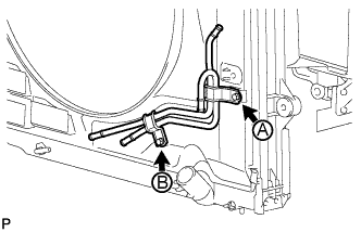
Temporarily install the oil cooler tube to the fan shroud with the bolt labeled A. Install the bolt labeled B. Then tighten the bolt labeled A to the specified torque.
- Torque:
- 5.0 N*m { 51 kgf*cm, 44 in.*lbf }
-
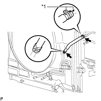
Text in Illustration *1 Paint Mark Connect the inlet No. 4 oil cooler hose as shown in the illustration.
Note
Make sure the pinching portion of each clip is facing the direction shown in the illustration.
-
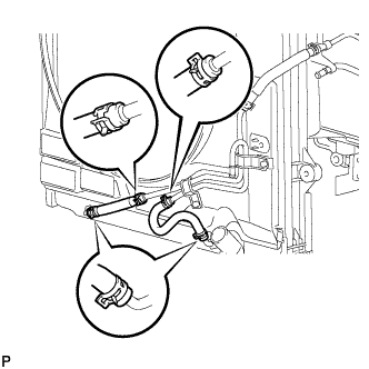
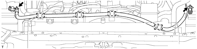
Connect the inlet No. 2 and No. 3 oil cooler hoses as shown in the illustration.
Note
Make sure the pinching portion of each clip is facing the direction shown in the illustration.
-
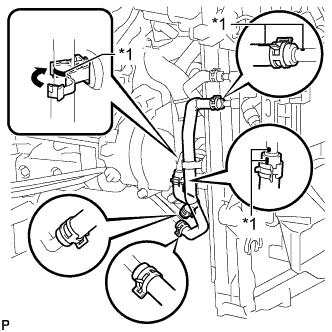
Text in Illustration *1 Paint Mark Connect the inlet and outlet No. 1 oil cooler hoses as shown in the illustration.
Note
Make sure the pinching portion of each clip is facing the direction shown in the illustration.
-
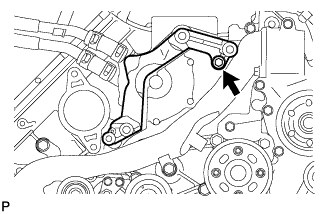
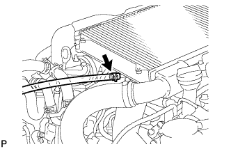
Pass the hose through the flexible hose clamp and close the clamp shown in the illustration.
-
-
INSTALL V-RIBBED BELT
-
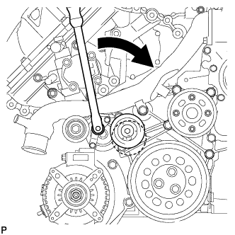
Attach a wrench to the V-ribbed belt tensioner bracket and turn the wrench clockwise.
-
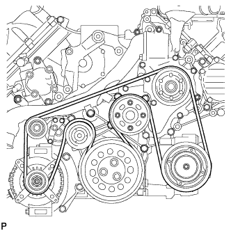
Install the V-ribbed belt as shown in the illustration.
-
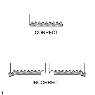
Check that the belt fits properly in the ribbed grooves.
Tech Tips
Check with your hand to confirm that the belt has not slipped out of the groove on the bottom of the pulley.
If it has slipped out, replace the V-ribbed belt. Install a new V-ribbed belt.
-
-
INSTALL NO. 3 IDLER PULLEY (w/ Viscous Heater)
-
Align the No. 3 idler pulley bracket knock pin and No. 1 idler pulley bracket knock pin hole and install the No. 3 idler pulley with the nut.
- Torque:
- 88 N*m { 898 kgf*cm, 64 ft.*lbf }
-
-
INSTALL NO. 1 IDLER PULLEY (w/ Viscous Heater)
-
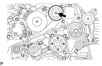
Install the collar, No. 1 idler pulley and cover with the bolt.
- Torque:
- 49 N*m { 495 kgf*cm, 36 ft.*lbf }
-
-
INSTALL V-RIBBED BELT (w/ Viscous Heater)
-
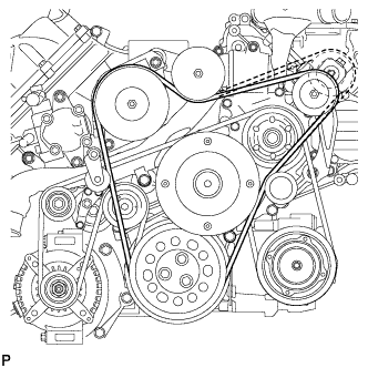
Install the V-ribbed belt as shown in the illustration.
-
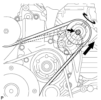
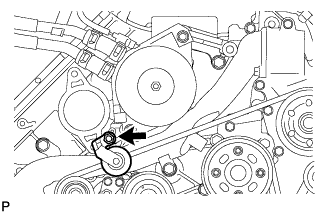
Temporarily install the lock nut, and turn the bolt clockwise.
-
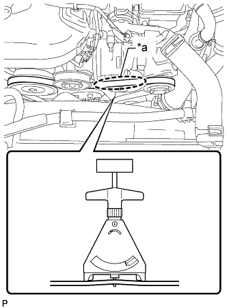
Text in Illustration *a Measuring Point Using a belt tension gauge, inspect the belt tension.
Standard Belt Tension Item Condition Specified Condition New belt 5 to 35°C (41 to 95°F) 550 to 800 N (56 to 82 kgf, 123.6 to 179.8 lbf) Used belt 5 to 35°C (41 to 95°F) 300 to 500 N (31 to 51 kgf, 67.4 to 112.4 lbf) Tech Tips
-
When measuring the tension of a new belt, measure the tension immediately after installing it to the engine but before starting the engine.
-
A "new belt" is a belt which has been used for less than 5 minutes on a running engine.
-
A "used belt" is a belt which has been used on a running engine for 5 minutes or more.
-
After installing a new belt, run the engine for approximately 5 minutes and then recheck the tension.
-
-
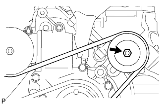
Tighten the nut.
- Torque:
- 40 N*m { 408 kgf*cm, 30 ft.*lbf }
-
Check that the belt fits properly in the ribbed grooves.
Tech Tips
Check with your hand to confirm that the belt has not slipped out of the groove on the bottom of the pulley.
If it has slipped out, replace the V-ribbed belt. Install a new V-ribbed belt.
-
-
CONNECT NO. 2 RADIATOR HOSE
-
CONNECT NO. 1 RADIATOR HOSE
-
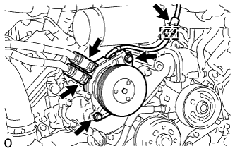
INSTALL VANE PUMP ASSEMBLY
-
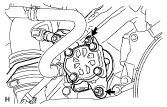
Apply a light coat of engine oil to a new O-ring, and install it to the vane pump.
-
Install the vane pump with 2 new nuts.
- Torque:
- 29 N*m { 296 kgf*cm, 21 ft.*lbf }
-
-
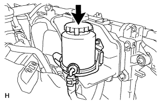
INSTALL RADIATOR RESERVOIR ASSEMBLY
-
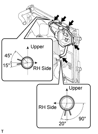
Install the radiator reservoir with the 3 bolts.
-
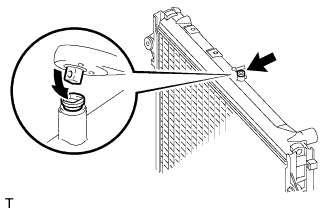
Connect the 2 hoses to the upper radiator tank and water inlet.
Tech Tips
Make sure the directions of the hose clamps are as shown in the illustration.
-
-
INSTALL NO. 1 OIL RESERVOIR BRACKET
-
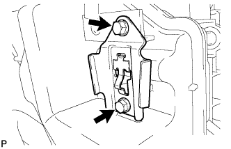
Install a new bracket with the 2 bolts.
- Torque:
- 4.5 N*m { 46 kgf*cm, 40 in.*lbf }
-
-
INSTALL VANE PUMP OIL RESERVOIR ASSEMBLY
-
Install the vane pump oil reservoir to the bracket.
-
-
INSTALL INTAKE AIR CONNECTOR
-
Connect the intake air connector to the No. 1 and No. 2 air cleaner pipes.
-
Install the connector with the 2 bolts.
- Torque:
- 21 N*m { 214 kgf*cm, 15 ft.*lbf }
-
Tighten the 2 hose clamps.
- Torque:
- 6.3 N*m { 64 kgf*cm, 56 in.*lbf }
-
Attach the 3 wire harness clamps.
-
w/o Viscous Heater:
Connect the connector to the water temperature sensor.
-
w/ Viscous Heater:
Connect the 2 connectors to the water temperature sensor and viscous with magnet clutch heater.
-
-
TEMPORARILY INSTALL NO. 1 AIR CLEANER HOSE
-
Temporarily install the air cleaner hose to the intake air connector.
-
-
INSTALL AIR CLEANER CAP SUB-ASSEMBLY
-
Connect the air cleaner cap to the air cleaner hose, and install the air cleaner cap with the 4 clamps.
-
Connect the mass air flow meter connector and attach the wire harness clamp to the air cleaner cap.
-
Attach the wire harness clamp.
-
Align the protrusion of the air cleaner cap and the concave portion of the air cleaner hose.
-
Tighten the 2 hose clamps.
- Torque:
- 2.5 N*m { 25 kgf*cm, 22 in.*lbf }
-
-
INSTALL NO. 1 ENGINE COVER SUB-ASSEMBLY (w/ Intercooler)
-
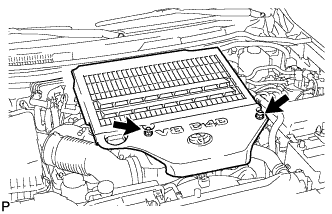
Install the engine cover with the 2 nuts.
- Torque:
- 8.0 N*m { 82 kgf*cm, 71 in.*lbf }
-
-
INSTALL NO. 3 ENGINE ROOM WIRE
-
Install the No. 3 engine room wire to the main battery and sub-battery positive terminals with the 2 nuts.
- Torque:
- 7.6 N*m { 77 kgf*cm, 67 in.*lbf }
-
Connect the No. 3 engine room wire with the 4 clamps.
-
-
CONNECT CABLE TO NEGATIVE BATTERY TERMINAL
Note
When disconnecting the cable, some systems need to be initialized after the cable is reconnected Click here.
-
Connect the cables to negative (-) main battery and sub-battery terminals.
-
-
ADD ENGINE COOLANT
-
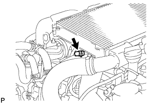
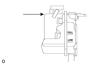
Remove the engine air bleed cap.
-
Connect a clear hose to the engine air bleed pipe.
-
Using a wrench, remove the vent plug.
-
Fill the radiator with TOYOTA SLLC to the radiator reservoir filler neck.
Tech Tips
Pour TOYOTA SLLC until it spills out of the engine air bleed pipe.
Standard Capacity (for Automatic Transmission) Item Specified Condition Front heater only 14.8 liters (15.6 US qts, 13.0 Imp. qts) Front heater and rear heater 17.6 liters (18.6 US qts, 15.5 Imp. qts) Front heater with viscous heater 15.2 liters (16.1 US qts, 13.4 Imp. qts) Front heater and rear heater with viscous heater 18.0 liters (19.0 US qts, 15.4 Imp. qts) Standard capacity (for Manual Transmission) 15.4 liters (16.3 US qts, 13.5 Imp. qts) Note
Do not substitute plain water for engine coolant.
Tech Tips
TOYOTA vehicles are filled with TOYOTA SLLC at the factory. In order to avoid damage to the engine cooling system and other technical problems, only use TOYOTA SLLC or similar high quality ethylene glycol based non-silicate, non-amine, non-nitrite, non-borate coolant with long-life hybrid organic acid technology (coolant with long-life hybrid organic acid technology consists of a combination of low phosphates and organic acids).
-
Install the vent plug.
- Torque:
- 2.0 N*m { 20 kgf*cm, 18 in.*lbf }
Note
Do not tighten the plug to 5.0 N*m (51 kgf*cm, 44 in.*lbf) or more, as the plug will be damaged.
-
Disconnect the clear hose from the engine air bleed pipe.
-
Install the engine air bleed cap when coolant comes out.
-
Install the radiator reservoir cap.
-
Start the engine.
Note
Immediately after starting the engine, if the radiator reservoir does not have any coolant, perform the following: 1) stop the engine, 2) wait until the coolant has cooled down, and 3) add coolant until the coolant is filled to the FULL line.
-
Maintain an engine speed of 3000 rpm for approximately 10 minutes so that the thermostat opens and air bleeding is performed.
CAUTION:
-
Wear protective gloves.
-
Be careful as the radiator hoses are hot.
-
Keep your hands away from the radiator fan
When pressing the radiator hoses:
Note
-
Pay attention to the needle of the water temperature meter. Make sure that the needle does not show an abnormally high temperature.
-
If there is not enough coolant, the engine may burn out or overheat.
Tech Tips
The thermostat opening timing can be confirmed by pressing the No. 2 radiator hose by hand, and checking when the engine coolant starts to flow inside the hose.
-
-
Stop the engine, and wait until the engine coolant cools down to ambient temperature.
CAUTION:
Do not remove the radiator reservoir cap while the engine and radiator are still hot. Pressurized, hot engine coolant and steam may be released and cause serious burns.
-
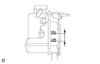
Check that the coolant level is between the FULL and LOW lines.
If the coolant level is above the FULL line, drain coolant so that the coolant level is between the FULL and LOW lines.
-
-
INSPECT FOR ENGINE COOLANT LEAK
CAUTION:
Do not remove the radiator reservoir cap while the engine and radiator are still hot. Pressurized, hot engine coolant and steam may be released and cause serious burns.
-
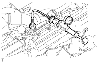
Fill the radiator with coolant and attach a radiator cap tester to the radiator reservoir.
-
Warm up the engine.
-
Using the radiator cap tester, increase the pressure inside the radiator to 123 kPa (1.3 kgf/cm2, 17.8 psi), and check that the pressure does not drop.
If the pressure drops, check the hoses, radiator and water pump for leaks.
If no external leaks are found, check the cylinder block and cylinder head.
-
-
INSTALL UPPER RADIATOR SUPPORT SEAL
-
Install the upper radiator support seal with the 7 clips.
-
-
INSTALL NO. 1 ENGINE UNDER COVER SUB-ASSEMBLY
-
Install the No. 1 engine under cover with the 10 bolts.
- Torque:
- 29 N*m { 296 kgf*cm, 21 ft.*lbf }
-
-
INSTALL FRONT FENDER SPLASH SHIELD SUB-ASSEMBLY RH
-
Install the front fender splash shield RH with the clip, and then install the 3 bolts and 2 screws.
-
-
INSTALL FRONT FENDER SPLASH SHIELD SUB-ASSEMBLY LH
-
Install the front fender splash shield LH with the clip, and then install the 3 bolts and screw.
-
-
INSTALL FRONT FENDER APRON SEAL FRONT RH
-
Install the front fender apron seal front RH with the 3 clips.
-
-
INSTALL FRONT WHEEL RH
- Torque:
- for Aluminum Wheel
- 131 N*m { 1336 kgf*cm, 97 ft.*lbf }
- for Steel Wheel
- 209 N*m { 2131 kgf*cm, 154 ft.*lbf }