WATER PUMP REMOVAL

-
REMOVE FRONT FENDER SPLASH SHIELD SUB-ASSEMBLY LH
-
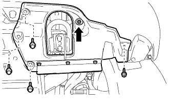
Remove the 3 bolts and screw.
-
Turn the clip indicated by the arrow in the illustration to remove the front fender splash shield sub-assembly LH.
-
-
REMOVE FRONT FENDER SPLASH SHIELD SUB-ASSEMBLY RH
-
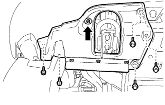
Remove the 3 bolts and 2 screws.
-
Turn the clip indicated by the arrow in the illustration to remove the front fender splash shield sub-assembly RH.
-
-
REMOVE NO. 1 ENGINE UNDER COVER SUB-ASSEMBLY
-
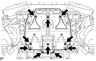
Remove the 10 bolts and No. 1 engine under cover.
-
-
DRAIN ENGINE COOLANT
CAUTION:
Do not remove the radiator cap while the engine and radiator are still hot. Pressurized, hot engine coolant and steam may be released and cause serious burns.
-
Loosen the radiator drain cock plug.
Tech Tips
Collect the coolant in a container and dispose of it according to the regulations in your area.
-
Remove the radiator cap. Then drain the coolant from the radiator.
-
Loosen the 2 cylinder block drain cock plugs. Then drain the coolant from the engine.
-
Tighten the 2 cylinder block drain cock plugs.
- Torque:
- 13 N*m { 133 kgf*cm, 10 ft.*lbf }
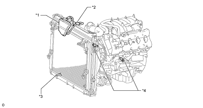
Text in Illustration *1 Radiator Reservoir *2 Radiator Cap *3 Radiator Drain Cock Plug *4 Cylinder Block Drain Cock Plug -
Tighten the radiator drain cock plug by hand.
-
-
REMOVE V-BANK COVER SUB-ASSEMBLY
-
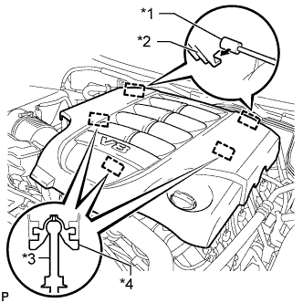
Text in Illustration *1 Bracket *2 Hook *3 Pin *4 Grommet Raise the front of the V-bank cover to detach the 3 pins. Then remove the 2 V-bank cover hooks from the bracket, and remove the V-bank cover.
-
-
REMOVE AIR CLEANER HOSE ASSEMBLY
-
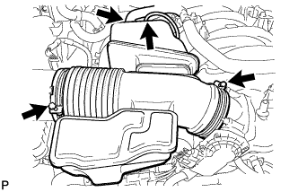
Disconnect the vacuum hose and No. 2 ventilation hose.
-
Loosen the 2 hose clamps.
-
Remove the air cleaner hose.
-
-
REMOVE AIR CLEANER ASSEMBLY
-
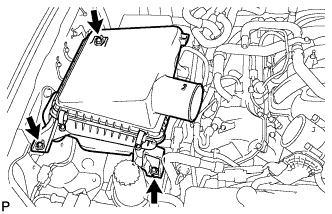
Remove the 3 bolts and air cleaner.
-
-
REMOVE NO. 1 RADIATOR HOSE
-
REMOVE NO. 2 RADIATOR HOSE
-
REMOVE FAN SHROUD
-

Loosen the 4 nuts holding the fluid coupling fan.
-
Remove the fan and generator V-belt Click here.
-
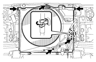
Disconnect the reservoir hose from the upper radiator tank.
-
Detach the claw to open the flexible hose clamp.
-
Remove the 2 bolts and disconnect the oil cooler tube from the fan shroud.
-
Remove the 2 bolts holding the fan shroud.
-
Remove the 4 nuts of the fluid coupling fan, and then remove the shroud together with the coupling fan.
Note
Be careful not to damage the radiator core.
-
Remove the fan pulley.
-
-
REMOVE NO. 1 WATER BY-PASS HOSE
-
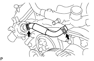
Remove the No. 1 water by-pass hose by disconnecting the hose from the water inlet housing and front water by-pass joint.
-
-
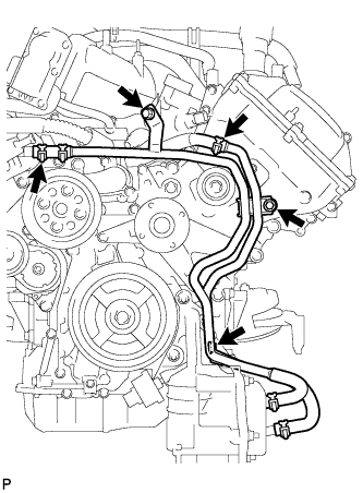
DISCONNECT NO. 2 WATER BY-PASS PIPE SUB-ASSEMBLY
-
Disconnect the No. 6 water by-pass hose.
-
Remove the 3 bolts.
-
Disconnect the water by-pass pipe with water hose.
-
-
REMOVE WATER INLET HOUSING
-
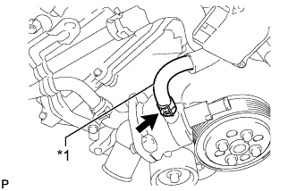
Text in Illustration *1 No. 5 Water By-pass Hose Disconnect the No. 5 water by-pass hose.
-
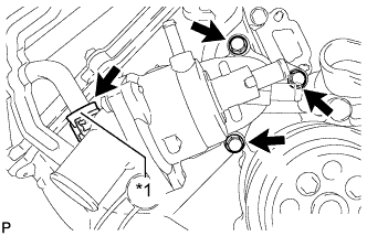
Text in Illustration *1 No. 3 Water By-pass Hose Disconnect the No. 3 water by-pass hose and remove the 3 bolts and water inlet housing.
-
Remove the gasket from the water pump.
-
-
REMOVE WATER PUMP PULLEY
-
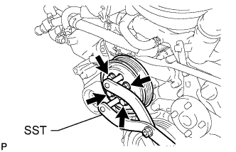
Using SST, hold the water pump pulley.
- SST
- 09960-10010 ( 09962-01000, 09963-01000 )
-
Remove the 4 bolts and water pump pulley.
-
-
REMOVE WATER PUMP ASSEMBLY
-
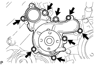
Remove the 8 bolts, water pump and gasket.
-