- Click here
INSTALL ENGINE WATER PUMP ASSEMBLY
-
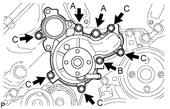
Install a new gasket and the engine water pump with the 8 bolts shown in the illustration.
for bolt A 47 N*m 479 kgf*cm 35 ft.*lbf for bolt B 23 N*m 235 kgf*cm 17 ft.*lbf for bolt C 20 N*m 204 kgf*cm 15 ft.*lbf Standard Bolt Item Length Thread Diameter Bolt A 80 mm (3.15 in.) 10 mm (0.394 in.) Bolt B 70 mm (2.76 in.) 8 mm (0.315 in.) Bolt C 25 mm (0.984 in.) 8 mm (0.315 in.)
-
- Click here
INSTALL WATER PUMP PULLEY
-
Temporarily install the water pump pulley with the 4 bolts.
-
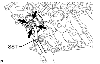
Using SST, hold the water pump pulley and tighten the 4 bolts.
09960-10010 09962-01000 09963-01000 21 N*m 214 kgf*cm 15 ft.*lbf
-
- Click here
INSTALL WATER INLET HOUSING
-
Install a new gasket to the engine water pump.
-
Install the water inlet housing with the 3 bolts.
21 N*m 214 kgf*cm 15 ft.*lbf
-
- Click here
CONNECT NO. 5 WATER BY-PASS HOSE
- Click here
INSTALL NO. 2 WATER BY-PASS PIPE SUB-ASSEMBLY
-
Connect the 4 hoses.
-
Install the water by-pass pipe with the 2 bolts.
10 N*m 102 kgf*cm 7 ft.*lbf
-
- Click here
INSTALL NO. 1 WATER BY-PASS HOSE
- Click here
CONNECT WATER BY-PASS HOSE
- Click here
INSTALL AIR TUBE SUB-ASSEMBLY (w/ Secondary Air Injection System)
-
Install the air tube.
-
Install the bolt.
10 N*m 102 kgf*cm 7 ft.*lbf -
Install the bracket with the 2 bolts.
10 N*m 102 kgf*cm 7 ft.*lbf -
Attach the clamp and connect the manifold absolute pressure sensor connector.
-
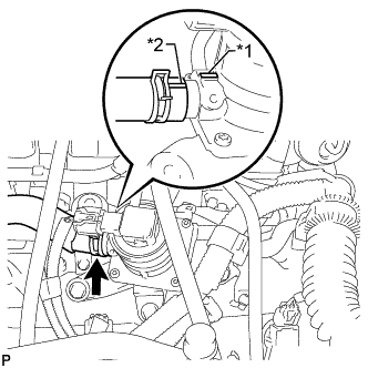
Align the paint mark with the projection and connect the No. 2 air injection system hose.
Table 1. Text in Illustration *1 Projection *2 Paint Mark Tip:Make sure the direction of the hose clamp is as shown in the illustration.
-
- Click here
INSTALL NO. 2 RADIATOR HOSE
- Click here
INSTALL FAN SHROUD
-
Install the fan pulley to the engine water pump.
-
Place the shroud together with the fluid coupling fan between the radiator and engine.
Note:Be careful not to damage the radiator core.
-
Temporarily install the fluid coupling fan to the fluid coupling bracket with the 4 nuts. Tighten the nuts as much as possible by hand.
-
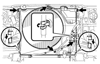
Attach the claws of the shroud to the radiator as shown in the illustration.
-
Install the shroud with the 2 bolts.
8.0 N*m 82 kgf*cm 71 in.*lbf -
Connect the oil cooler tube to the fan shroud with the 2 bolts.
5.0 N*m 51 kgf*cm 44 in.*lbf -
w/ Air Cooled Transmission Oil Cooler:
Pass the hose through the flexible hose clamp and close the clamp as shown in the illustration.
-
Connect the reservoir hose to the upper radiator tank.
-
Install the fan and generator V belt (Click here).
-
Tighten the 4 nuts of the fluid coupling fan.
21 N*m 214 kgf*cm 15 ft.*lbf
-
- Click here
INSTALL NO. 1 RADIATOR HOSE
- Click here
INSTALL AIR CLEANER CAP AND HOSE
-
Install the air cleaner cap and hose, and then tighten the hose clamp.
2.5 N*m 25 kgf*cm 22 in.*lbf -
Attach the 4 clamps.
-
Connect the mass air flow meter connector and attach the clamp.
-
Connect the No. 2 PCV hose and No. 1 air hose.
-
- Click here
INSTALL V-BANK COVER SUB-ASSEMBLY
-
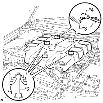
Attach the 2 V-bank cover hooks to the bracket. Then align the 3 V-bank cover grommets with the 3 pins, and press down on the V-bank cover to attach the pins.
Table 2. Text in Illustration *1 Grommet *2 Pin *3 Hook *4 Bracket
-
- Click here
ADD ENGINE COOLANT
-
Add engine coolant.
Standard Capacity (w/o ATF Warmer) Item Specified Condition w/ Rear Heater 16.5 liters (17.4 US qts, 14.5 Imp. qts) w/o Rear Heater 13.8 liters (14.6 US qts, 12.1 Imp. qts) Standard Capacity (w/ ATF Warmer) Item Specified Condition w/ Rear Heater 17.0 liters (18.0 US qts, 15.0 Imp. qts) w/o Rear Heater 14.2 liters (15.0 US qts, 12.5 Imp. qts) Note:Do not substitute plain water for engine coolant.
Tip:
-
TOYOTA vehicles are filled with TOYOTA SLLC at the factory. In order to avoid damage to the engine cooling system and other technical problems, only use TOYOTA SLLC or similar high quality ethylene glycol based non-silicate, non-amine, non-nitrite, non-borate coolant with long-life hybrid organic acid technology (coolant with long-life hybrid organic acid technology consists of a combination of low phosphates and organic acids).
-
Press the No. 1 and No. 2 radiator hoses several times by hand, and then check the coolant level. If the coolant level is low, add coolant.
-
-
Slowly pour coolant into the radiator reservoir until it reaches the F line.
-
Install the reservoir cap.
-
Install the radiator cap.*1
-
Start the engine and stop it immediately.*2
-
Allow approximately 10 seconds to pass. Then remove the radiator cap and check the coolant level. If the coolant level has decreased, add coolant.*3
-
Repeat steps *1, *2 and *3 until the coolant level does not decrease.
Tip:Be sure to perform this step while the engine is cold, as air in the No. 1 radiator hose will flow into the radiator if the engine is warmed up and the thermostat opens.
-
Install the radiator cap.*4
-
Set the air conditioning as follows.*5
Item Condition Fan speed Any setting except off Temperature Toward WARM Air conditioning switch Off -
Start the engine, warm it up until the thermostat opens, and then continue to run the engine for several minutes to circulate the coolant.*6
CAUTION:
-
Wear protective gloves. Hot areas on the parts may injure your hands.
-
Be careful of the fan.
-
Be careful as the engine, radiator and radiator hoses are hot and can cause burns.
Note:
-
Immediately after starting the engine, if the radiator reservoir does not have any coolant, perform the following: 1) stop the engine, 2) wait until the coolant has cooled down, and 3) add coolant until the coolant is filled to the F line.
-
Do not start the engine when there is no coolant in the radiator reservoir.
-
Pay attention to the needle of the engine coolant temperature receiver gauge. Make sure that the needle does not show an abnormally high temperature.
-
If there is not enough coolant, the engine may burn out or overheat.
Tip:
-
Press the No. 1 and No. 2 radiator hoses several times by hand to bleed air while warming up the engine.
-
The thermostat opening timing can be confirmed by pressing the No. 2 radiator hose by hand and checking when the engine coolant starts to flow inside the hose.
-
-
Stop the engine, wait until the engine coolant cools down to ambient temperature. Then remove the radiator cap and check the coolant level.*7
CAUTION:Do not remove the radiator cap while the engine and radiator are still hot. Pressurized, hot engine coolant and steam may be released and cause serious burns.
-
If the coolant level has decreased, add coolant and warm up the engine until the thermostat opens.*8
-
If the coolant level has not decreased, check that the coolant level in the radiator reservoir is at the F line.
If the coolant level is below the F line, repeat steps *4 through *8.
If the coolant level is above the F line, drain coolant until the coolant level reaches the F line.
-
- Click here
INSPECT FOR COOLANT LEAK
CAUTION:To avoid being burned, do not remove the radiator reservoir cap while the engine and radiator are still hot. Thermal expansion may cause hot engine coolant and steam to blow out from the radiator.
-
Remove the radiator cap.
-
Check for excessive deposits of rust or scales around the radiator reservoir cap and radiator reservoir filler hole. Also, the engine coolant should be free of oil.
If excessively dirty, replace the engine coolant.
-
Install the radiator cap.
-
- Click here
INSTALL NO. 1 ENGINE UNDER COVER SUB-ASSEMBLY
-
Install the No. 1 engine under cover sub-assembly with the 10 bolts.
29 N*m 296 kgf*cm 21 ft.*lbf
-
- Click here
INSTALL FRONT FENDER SPLASH SHIELD SUB-ASSEMBLY LH
-
Push in the clip to install the front fender splash shield sub-assembly LH.
-
Install the 3 bolts and screw.
-
- Click here
INSTALL FRONT FENDER SPLASH SHIELD SUB-ASSEMBLY RH
-
Push in the clip to install the front fender splash shield sub-assembly RH.
-
Install the 3 bolts and 2 screws.
-
- Click here
INSTALL COOLER COMPRESSOR ASSEMBLY