EXHAUST MANIFOLD W/ TURBOCHARGER INSTALLATION

Note
w/ DPF:
When fuel lines are disconnected, air may enter the fuel lines, leading to engine starting trouble. Therefore, perform forced regeneration and bleed the air from the fuel lines Click here.
-
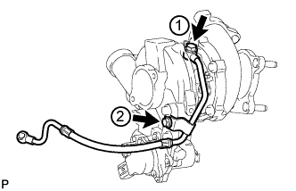
INSTALL NO. 2 INLET TURBO OIL PIPE SUB-ASSEMBLY (for Bank 2)
-
Temporarily install a new gasket and the No. 2 inlet turbo oil pipe with the union bolt and bolt.
-
Tighten the union bolt and bolt in the order shown in the illustration.
- Torque:
- for union bolt
- 29 N*m { 296 kgf*cm, 21 ft.*lbf }
- for bolt
- 10 N*m { 102 kgf*cm, 7 ft.*lbf }
-
-
INSTALL NO. 2 TURBO OIL PIPE (for Bank 2)
-
Install a new gasket and the No. 2 turbo oil pipe with the 2 bolts.
- Torque:
- 10 N*m { 102 kgf*cm, 7 ft.*lbf }
Tech Tips
The gasket claws should face the pipe.
-
-
INSTALL NO. 2 INLET COMPRESSOR ELBOW (for Bank 2)
-
Install a new gasket and the No. 2 inlet compressor elbow with the 2 bolts.
- Torque:
- 21 N*m { 214 kgf*cm, 15 ft.*lbf }
Tech Tips
Install the No. 2 inlet compressor elbow with the "L" mark facing toward the outside of the vehicle.
-
-
INSTALL NO. 2 TURBOCHARGER SUB-ASSEMBLY WITH EXHAUST MANIFOLD LH (for Bank 2)
-
Install a new gasket to the No. 2 turbocharger.
-
Install the exhaust manifold LH to the No. 2 turbocharger with 3 new nuts.
- Torque:
- 69 N*m { 704 kgf*cm, 51 ft.*lbf }
Tech Tips
The gasket claw should face toward the outside of the vehicle.
-
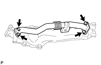
w/ DPF:
-
Install 2 new gaskets to the No. 2 exhaust manifold pipe.
Tech Tips
The gasket claws should face the No. 2 exhaust manifold pipe.
-
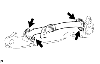
Temporarily install the No. 2 exhaust manifold pipe with the 4 bolts.
Tech Tips
Install the No. 2 exhaust manifold pipe so that it is oriented as shown in the illustration.
-
Tighten the 4 bolts.
- Torque:
- 21 N*m { 214 kgf*cm, 15 ft.*lbf }
-
-
Install a new gasket to the cylinder head LH.
-
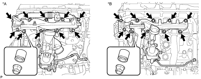
Install the No. 2 turbocharger with exhaust manifold LH and 10 collars to the cylinder head LH with 10 new nuts.
- Torque:
- 36 N*m { 367 kgf*cm, 27 ft.*lbf }
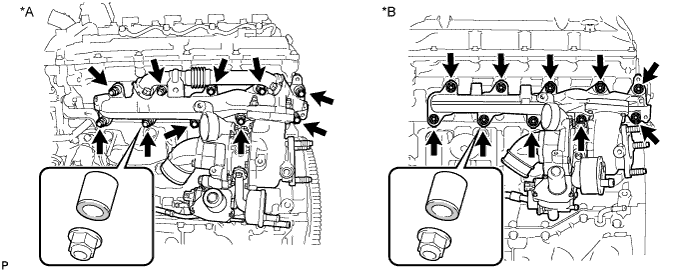
Text in Illustration *A w/ DPF *B w/o DPF Tech Tips
Install the collars with the colored side facing the nuts.
-
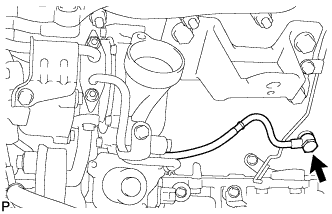
Install a new gasket and the No. 2 inlet turbo oil pipe to the No. 1 oil pan with the union bolt.
- Torque:
- 29 N*m { 296 kgf*cm, 21 ft.*lbf }
-
Connect the 2 connectors to the turbocharger.
-
-
INSTALL NO. 2 VENTILATION TUBE SUB-ASSEMBLY (for Bank 2)
-
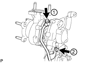
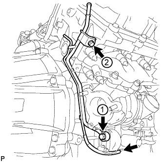
Temporarily install a new gasket and the No. 2 ventilation tube with the union bolt and bolt.
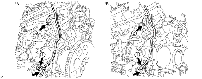
Text in Illustration *A w/ DPF *B w/o DPF -
Tighten the union bolt and bolt in the order shown in the illustration.
- Torque:
- for union bolt
- 29 N*m { 296 kgf*cm, 21 ft.*lbf }
- for bolt
- 10 N*m { 102 kgf*cm, 7 ft.*lbf }
Note
Clean and remove any oil in the area labeled 1 in the illustration.
-
Connect the hose.
-
-
INSTALL NO. 2 TURBOCHARGER STAY (for Bank 2)
-
Install the No. 2 turbocharger stay with the 2 bolts.
- Torque:
- 49 N*m { 495 kgf*cm, 36 ft.*lbf }
-
-
INSTALL NO. 2 OUTLET TURBO OIL HOSE (for Bank 2)
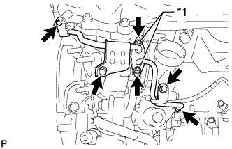
Tech Tips
Align the white paint marks on the oil hose and pipe, and connect the hose.
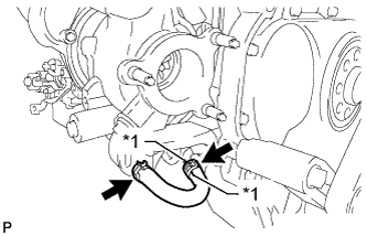
Text in Illustration *1 Painted Mark -
INSTALL NO. 2 TURBO WATER PIPE SUB-ASSEMBLY (for Bank 2)
-
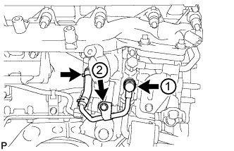
Temporarily install a new gasket and the No. 2 turbo water pipe with the union bolt and bolt.
-
Tighten the union bolt and bolt in the order shown in the illustration.
- Torque:
- for union bolt
- 35 N*m { 357 kgf*cm, 26 ft.*lbf }
- for bolt
- 10 N*m { 102 kgf*cm, 7 ft.*lbf }
-
Connect the water hose to the pipe.
-
-
INSTALL FRONT WATER BY-PASS JOINT (for Bank 2)
-
Install a new gasket and the front water by-pass joint.
- Torque:
- 50 N*m { 510 kgf*cm, 37 ft.*lbf }
-
-
INSTALL NO. 3 TURBO WATER PIPE SUB-ASSEMBLY (for Bank 2)
-
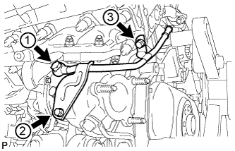
Temporarily install a new gasket and the No. 3 turbo water pipe with the union bolt and 2 bolts.
-
Tighten the union bolt and 2 bolts in the order shown in the illustration.
- Torque:
- for union bolt
- 35 N*m { 357 kgf*cm, 26 ft.*lbf }
- for bolt
- 10 N*m { 102 kgf*cm, 7 ft.*lbf }
-
-
INSTALL NO. 2 EXHAUST MANIFOLD HEAT INSULATOR (for Bank 2)
-
Install the No. 2 exhaust manifold heat insulator with the 3 bolts.
- Torque:
- 25 N*m { 255 kgf*cm, 18 ft.*lbf }
-
-
INSTALL NO. 2 TURBO WATER HOSE (for Bank 2)
-
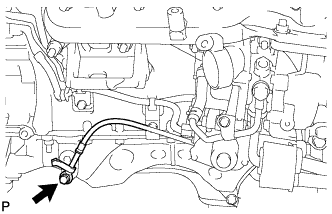
INSTALL BREATHER PLUG LH (for Bank 2)
-
Install the breather plug LH.
-
w/o DPF:
Attach the clamp.
-
Connect the hose.
-
-
INSTALL NO. 3 VENTILATION HOSE (for Bank 2)
-
INSTALL NO. 1 INLET TURBO OIL PIPE SUB-ASSEMBLY (for Bank 1)
-
Temporarily install a new gasket and the No. 1 inlet turbo oil pipe with the union bolt and bolt.
-
Tighten the union bolt and bolt in the order shown in the illustration.
- Torque:
- for union bolt
- 29 N*m { 296 kgf*cm, 21 ft.*lbf }
- for bolt
- 10 N*m { 102 kgf*cm, 7 ft.*lbf }
-
-
INSTALL NO. 1 TURBO OIL PIPE (for Bank 1)
-
Install a new gasket and the No. 1 turbo oil pipe with the 2 bolts.
- Torque:
- 10 N*m { 102 kgf*cm, 7 ft.*lbf }
-
-
INSTALL NO. 1 INLET COMPRESSOR ELBOW (for Bank 1)
-
Install a new gasket and the No. 1 inlet compressor elbow with the 2 bolts.
- Torque:
- 21 N*m { 214 kgf*cm, 15 ft.*lbf }
Tech Tips
Install the No. 1 inlet compressor elbow with the "R" mark facing toward the outside of the vehicle.
-
-
INSTALL NO. 1 TURBOCHARGER SUB-ASSEMBLY WITH EXHAUST MANIFOLD RH (for Bank 1)
-
Install a new gasket to the No. 1 turbocharger.
-
Install the exhaust manifold RH to the No. 1 turbocharger with 2 new nuts and the bolt.
- Torque:
- 69 N*m { 704 kgf*cm, 51 ft.*lbf }
-
w/ DPF:
-
Install 2 new gaskets to the No. 1 exhaust manifold pipe.
Tech Tips
The gasket claws should face the No. 1 exhaust manifold pipe.
-
Temporarily install the No. 1 exhaust manifold pipe with the 4 bolts.
Tech Tips
Install the No. 1 exhaust manifold pipe so that it is oriented as shown in the illustration.
-
Tighten the 4 bolts.
- Torque:
- 21 N*m { 214 kgf*cm, 15 ft.*lbf }
-
-
Install a new gasket to the cylinder head RH.
-
Install the No. 1 turbocharger with exhaust manifold RH to the cylinder head RH with the 10 collars and 10 new nuts.
- Torque:
- 36 N*m { 367 kgf*cm, 27 ft.*lbf }
Text in Illustration *A w/ DPF *B w/o DPF Tech Tips
Install the collars with the colored side facing the nuts.
-
Install a new gasket and the No. 1 inlet turbo oil pipe to the cylinder block with the union bolt.
- Torque:
- When "dry"
- 29 N*m { 296 kgf*cm, 21 ft.*lbf }
- When "wet"
- 23 N*m { 235 kgf*cm, 17 ft.*lbf }
Note
-
The parts are "dry" when there is absolutely no engine oil on the union bolt and cylinder block bolt hole.
-
The parts are "wet" when there is engine oil on the union bolt and cylinder block bolt hole.
-
-
INSTALL NO. 1 VENTILATION TUBE SUB-ASSEMBLY (for Bank 1)
-
Temporarily install a new gasket and the No. 1 ventilation tube with the union bolt and bolt.
-
Tighten the union bolt and bolt in the order shown in the illustration.
- Torque:
- for union bolt
- 29 N*m { 296 kgf*cm, 21 ft.*lbf }
- for bolt
- 10 N*m { 102 kgf*cm, 7 in.*lbf }
Note
Clean and remove any oil in the area labeled 1 in the illustration.
-
Connect the hose.
-
-
INSTALL NO. 1 TURBOCHARGER STAY (for Bank 1)
-
Temporarily install the No. 1 turbocharger stay with the 2 bolts.
-
Tighten the 2 bolts.
- Torque:
- 49 N*m { 495 kgf*cm, 36 ft.*lbf }
-
-
INSTALL NO. 1 TURBO WATER PIPE SUB-ASSEMBLY (for Bank 1)
-
Text in Illustration *1 New Nut Install a new gasket and the No. 1 turbo water pipe with 2 new nuts and the 3 bolts.
- Torque:
- 10 N*m { 102 kgf*cm, 7 ft.*lbf }
-
Connect the water hose.
-
-
CONNECT NO. 1 OUTLET TURBO OIL HOSE (for Bank 1)
-
INSTALL NO. 1 EXHAUST MANIFOLD HEAT INSULATOR (for Bank 1)
-
Install the No. 1 exhaust manifold heat insulator with the 3 bolts.
- Torque:
- 25 N*m { 255 kgf*cm, 18 ft.*lbf }
-
-
INSTALL NO. 2 TURBO WATER HOSE (for Bank 1)
-
INSTALL BREATHER PLUG RH (for Bank 1)
-
Install the breather plug RH and attach the clamp.
-
Connect the hose.
-
-
INSTALL NO. 2 VENTILATION HOSE (for Bank 1)
-
INSTALL NO. 1 INTAKE AIR CONNECTOR PIPE (for Bank 1)
-
Install the No. 1 intake air connector pipe with the bolt. Then tighten the hose clamp.
- Torque:
- for bolt
- 21 N*m { 214 kgf*cm, 15 ft.*lbf }
- for hose clamp
- 6.0 N*m { 61 kgf*cm, 53 in.*lbf }
-
Connect the 4 connectors and attach the 5 wire harness clamps.
-
-
INSTALL NO. 1 ENGINE OIL LEVEL DIPSTICK GUIDE (for Bank 1)
-
Apply a light coat of engine oil to a new O-ring and install it to the No. 1 engine oil level dipstick guide.
-
Install the No. 1 engine oil level dipstick guide with the 2 bolts.
- Torque:
- 10 N*m { 102 kgf*cm, 7 ft.*lbf }
-
-
INSTALL ENGINE ASSEMBLY
-
INSPECT FOR OIL LEAK
-
Warm up the engine and check for an engine oil leak.
-
-
INSPECT FOR COOLANT LEAK
CAUTION:
Do not remove the radiator reservoir cap while the engine and radiator are still hot. Pressurized, hot engine coolant and steam may be released and cause serious burns.
-
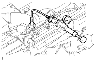
Fill the radiator with coolant and attach a radiator cap tester to the radiator reservoir.
-
Warm up the engine.
-
Using the radiator cap tester, increase the pressure inside the radiator to 123 kPa (1.3 kgf/cm2, 17.8 psi), and check that the pressure does not drop.
If the pressure drops, check the hoses, radiator and water pump for leaks.
If no external leaks are found, check the cylinder block and cylinder head.
-
-
CHECK ENGINE OIL LEVEL
-
Warm up the engine, stop the engine and wait 5 minutes. The engine oil level should be between the dipstick low level mark and full level mark.
If low, check for leakage and add oil up to the full level mark.
Note
Do not fill engine oil above the full level mark.
Tech Tips
A certain amount of engine oil will be consumed while driving. In the following situations, oil consumption may increase, and engine oil may need to be refilled in between oil maintenance intervals.
-
When the engine is new, for example directly after purchasing the vehicle or after replacing the engine.
-
If low quality oil or oil of an inappropriate viscosity is used.
-
When driving at high engine speed or with a heavy load, (when towing, or), when driving while accelerating or decelerating frequently.
-
When leaving the idling for a long time, or when driving frequently through heavy traffic.
When judging the amount of oil consumption, keep in mind that the oil may have become diluted, making it difficult to judge the true level accurately.
-
-
-
CONNECT CABLE TO NEGATIVE BATTERY TERMINAL
Note
When disconnecting the cable, some systems need to be initialized after the cable is reconnected Click here.
-
Connect the cables to negative (-) main battery and sub-battery terminals.
-
-
PERFORM TURBOCHARGER INITIALIZATION