- Click here
REMOVE V-BANK COVER SUB-ASSEMBLY
-
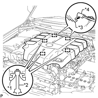
Raise the front of the V-bank cover to detach the 3 pins. Then remove the 2 V-bank cover hooks from the bracket, and remove the V-bank cover.
Table 1. Text in Illustration *1 Grommet *2 Pin *3 Hook *4 Bracket
-
- Click here
REMOVE AIR CLEANER AND HOSE
-
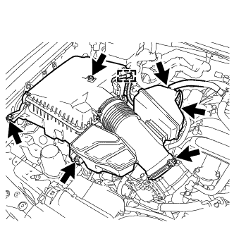
Disconnect the No. 2 PCV hose and No. 1 air hose.
-
Disconnect the mass air flow meter connector and detach the clamp.
-
Remove the 3 bolts and loosen the hose clamp, and then remove the air cleaner and hose.
-
- Click here
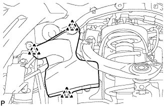
REMOVE FRONT FENDER SPLASH SHIELD SUB-ASSEMBLY LH
-
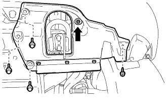
Remove the 3 bolts and screw.
-
Turn the clip indicated by the arrow in the illustration to remove the front fender splash shield sub-assembly LH.
-
- Click here
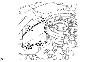
REMOVE FRONT FENDER SPLASH SHIELD SUB-ASSEMBLY RH
-
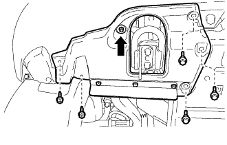
Remove the 3 bolts and 2 screws.
-
Turn the clip indicated by the arrow in the illustration to remove the front fender splash shield sub-assembly RH.
-
- Click here
REMOVE NO. 1 ENGINE UNDER COVER SUB-ASSEMBLY
-
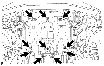
Remove the 10 bolts and No. 1 engine under cover sub-assembly.
-
- Click here
REMOVE NO. 2 ENGINE UNDER COVER
-
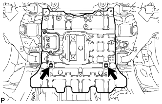
Remove the 2 bolts and No. 2 engine under cover.
-
- Click here
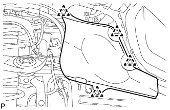
REMOVE FRONT FENDER APRON TRIM PACKING B
-
w/ KDSS:
Remove the 3 clips and front fender apron trim packing B.
-
w/o KDSS:
Remove the 4 clips and front fender apron trim packing B.
-
- Click here
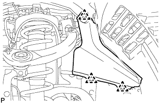
REMOVE FRONT FENDER APRON TRIM PACKING D
-
Remove the 4 clips and front fender apron trim packing D.
-
- Click here
REMOVE FRONT FENDER APRON TRIM PACKING A
-
Remove the 3 clips and front fender apron trim packing A.
-
- Click here
REMOVE FRONT FENDER APRON TRIM PACKING C
-
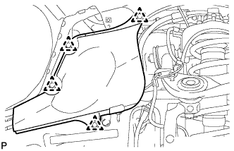
Remove the 4 clips and front fender apron trim packing C.
-
- Click here
REMOVE FRONT EXHAUST PIPE ASSEMBLY
- Click here
REMOVE FRONT PROPELLER SHAFT ASSEMBLY
- Click here
REMOVE PROPELLER SHAFT HEAT INSULATOR
-
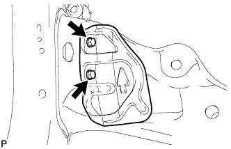
Remove the 2 bolts and heat insulator.
-
- Click here
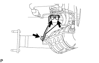
REMOVE NO. 2 MANIFOLD STAY
-
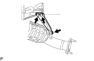
Remove the 3 bolts and No. 2 manifold stay.
-
- Click here
REMOVE NO. 2 EXHAUST MANIFOLD HEAT INSULATOR
-
Remove the 3 bolts and No. 2 exhaust manifold heat insulator.
-
- Click here
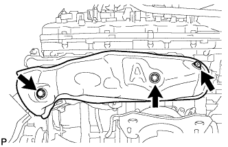
REMOVE EXHAUST MANIFOLD ASSEMBLY LH
-
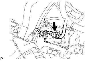
Disconnect the air fuel ratio sensor connector and detach the wire harness clamp.
-
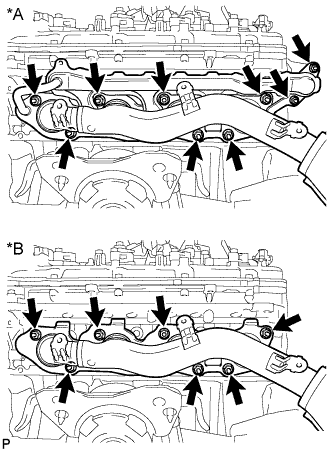
w/ Secondary Air Injection System:
Remove the 9 nuts, exhaust manifold and 2 gaskets.
Table 2. Text in Illustration *A w/ Secondary Air Injection System *B w/o Secondary Air Injection System -
w/o Secondary Air Injection System:
Remove the 7 nuts, exhaust manifold and gasket.
-
- Click here
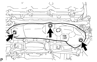
REMOVE MANIFOLD STAY
-
Remove the 3 bolts and manifold stay.
-
- Click here
REMOVE ENGINE OIL LEVEL DIPSTICK GUIDE
-
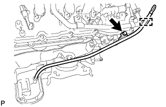
Remove the engine oil level dipstick.
-
Detach the engine wire clamp.
-
Remove the bolt and engine oil level dipstick guide.
-
Remove the O-ring from the engine oil level dipstick guide.
-
- Click here
REMOVE NO. 1 EXHAUST MANIFOLD HEAT INSULATOR
-
Remove the 3 bolts and heat insulator.
-
- Click here
REMOVE EXHAUST MANIFOLD ASSEMBLY RH
-
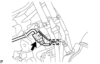
Disconnect the air fuel ratio sensor connector and detach the wire harness clamp.
-
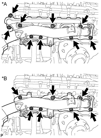
w/ Secondary Air Injection System:
Remove the 9 nuts, exhaust manifold and 2 gaskets.
Table 3. Text in Illustration *A w/ Secondary Air Injection System *B w/o Secondary Air Injection System -
w/o Secondary Air Injection System:
Remove the 7 nuts, exhaust manifold and 2 gaskets.
-
- Click here
REMOVE AIR FUEL RATIO SENSOR (for Bank 1 Sensor 1)
-
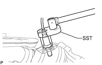
Using SST, remove the air fuel ratio sensor from the exhaust manifold LH.
09224-00010
-
- Click here
REMOVE AIR FUEL RATIO SENSOR (for Bank 2 Sensor 1)
-
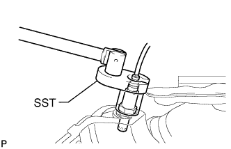
Using SST, remove the air fuel ratio sensor from the exhaust manifold RH.
09224-00010
-