- Click here
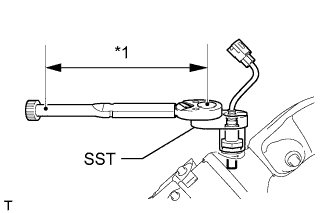
INSTALL AIR FUEL RATIO SENSOR (for Bank 2 Sensor 1)
-
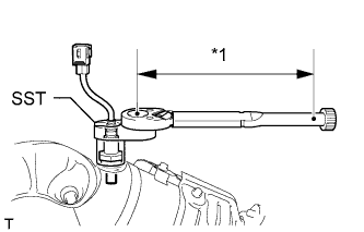
Using SST, install the air fuel ratio sensor.
09224-00010 without SST 44 N*m 449 kgf*cm 32 ft.*lbf with SST 40 N*m 408 kgf*cm 30 ft.*lbf Table 1. Text in Illustration *1 Fulcrum Length Tip:
-
Use a torque wrench with a fulcrum length of 300 mm (11.8 in.). When using a torque wrench with a fulcrum length that is not 300 mm (11.8 in.), calculate the torque specification for the torque wrench and SST based on the "without SST" torque specification (Click here).
-
Make sure SST and the wrench are connected in a straight line.
-
-
- Click here
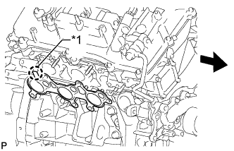
INSTALL EXHAUST MANIFOLD SUB-ASSEMBLY LH
-
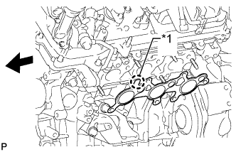
Install a new gasket to the cylinder head.
Table 2. Text in Illustration *1 Protrusion 
Front Note:Be careful of the installation direction.
-
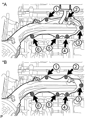
Temporarily install the manifold with 6 new nuts.
-
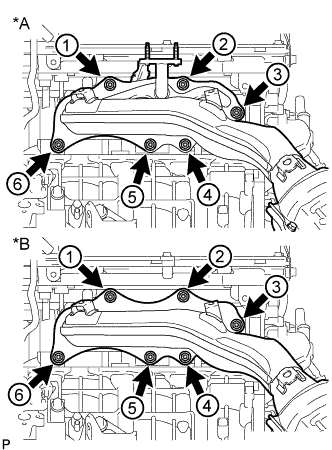
Tighten the 6 nuts in the sequence shown in the illustration.
21 N*m 214 kgf*cm 15 ft.*lbf Table 3. Text in Illustration *A w/ Secondary Air Injection System *B w/o Secondary Air Injection System -
Connect the air fuel ratio sensor connector.
-
- Click here
INSTALL NO. 2 EXHAUST MANIFOLD HEAT INSULATOR
-
Install the heat insulator with the 3 bolts.
13 N*m 133 kgf*cm 10 ft.*lbf
-
- Click here
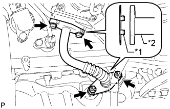
INSTALL NO. 2 AIR TUBE (w/ Secondary Air Injection System)
-
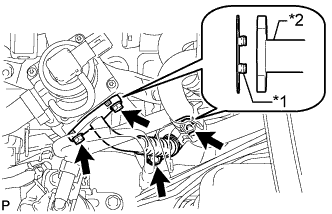
Install 2 new gaskets.
Table 4. Text in Illustration *1 Claw *2 No. 2 Air Tube Note:Make sure the gasket's claws are not caught between the No. 2 emission control valve set and No. 2 air tube.
-
Install the No. 2 air tube with the 2 bolts and 2 nuts.
10 N*m 102 kgf*cm 7 ft.*lbf
-
- Click here
INSTALL NO. 2 MANIFOLD STAY
-
Install the No. 2 manifold stay with the 3 bolts.
40 N*m 408 kgf*cm 30 ft.*lbf
-
- Click here
INSTALL AIR FUEL RATIO SENSOR (for Bank 1 Sensor 1)
-
Using SST, install the air fuel ratio sensor.
09224-00010 without SST 44 N*m 449 kgf*cm 32 ft.*lbf with SST 40 N*m 408 kgf*cm 30 ft.*lbf Table 5. Text in Illustration *1 Fulcrum Length Tip:
-
Use a torque wrench with a fulcrum length of 300 mm (11.8 in.). When using a torque wrench with a fulcrum length that is not 300 mm (11.8 in.), calculate the torque specification for the torque wrench and SST based on the "without SST" torque specification (Click here).
-
Make sure SST and the wrench are connected in a straight line.
-
-
- Click here
INSTALL EXHAUST MANIFOLD SUB-ASSEMBLY RH
-
Install a new gasket to the cylinder head.
Table 6. Text in Illustration *1 Protrusion Front Note:Be careful of the installation direction.
-
Temporarily install the manifold with 6 new nuts.
-
Tighten the 6 nuts in the sequence shown in the illustration.
21 N*m 214 kgf*cm 15 ft.*lbf Table 7. Text in Illustration *A w/ Secondary Air Injection System *B w/o Secondary Air Injection System -
Connect the air fuel ratio sensor connector.
-
- Click here
INSTALL NO. 1 EXHAUST MANIFOLD HEAT INSULATOR
-
Install the heat insulator with the 3 bolts.
13 N*m 133 kgf*cm 10 ft.*lbf
-
- Click here
CONNECT NO. 2 STEERING INTERMEDIATE SHAFT SUB-ASSEMBLY
-
for Manual Tilt and Manual Telescopic Steering Column: (Click here)
-
for Power Tilt and Power Telescopic Steering Column: (Click here)
-
- Click here
INSTALL AIR TUBE (w/ Secondary Air Injection System)
-
Install 2 new gaskets.
Table 8. Text in Illustration *1 Claw *2 Air Tube Note:Make sure the gasket's claws are not caught between the No. 1 emission control valve set and air tube.
-
Install the air tube with the 2 bolts and 2 nuts.
10 N*m 102 kgf*cm 7 in.*lbf
-
- Click here
INSTALL MANIFOLD STAY
-
Install the manifold stay with the 3 bolts.
40 N*m 408 kgf*cm 30 ft.*lbf
-
- Click here
INSTALL FRONT EXHAUST PIPE ASSEMBLY
- Click here
INSTALL NO. 2 ENGINE UNDER COVER
-
Install the No. 2 engine under cover with the 2 bolts.
29 N*m 296 kgf*cm 21 ft.*lbf
-
- Click here
INSTALL NO. 1 ENGINE UNDER COVER SUB-ASSEMBLY
-
Install the No. 1 engine under cover with the 10 bolts.
29 N*m 296 kgf*cm 21 ft.*lbf
-
- Click here
INSTALL FRONT FENDER SPLASH SHIELD SUB-ASSEMBLY RH
-
Push in the clip to install the front fender splash shield sub-assembly RH.
-
Install the 3 bolts and 2 screws.
-
- Click here
INSTALL FRONT FENDER SPLASH SHIELD SUB-ASSEMBLY LH
-
Push in the clip to install the front fender splash shield sub-assembly LH.
-
Install the 3 bolts and screw.
-
- Click here
INSTALL AIR CLEANER CASE SUB-ASSEMBLY
-
Install the air cleaner case with the 3 bolts.
5.0 N*m 51 kgf*cm 44 in.*lbf -
Install the air cleaner filter element.
-
- Click here
INSTALL AIR CLEANER CAP AND HOSE
-
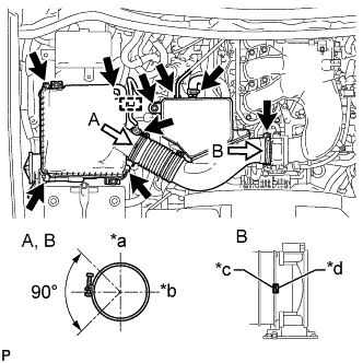
Install the air cleaner cap and hose.
Table 9. Text in Illustration *a Top *b Front *c Protrusion (Hose) *d Protrusion (Throttle body)
-
Install the air cleaner cap and hose with the bolt and fasten the 4 hook clamps.
5.0 N*m 51 kgf*cm 44 in.*lbf -
Tighten the clamp.
2.5 N*m 25 kgf*cm 22 in.*lbf -
Attach the 4 clamps and connect the No. 2 PCV hose, vacuum hose and mass air flow meter connector.
Tip:The direction of the hose clamp is indicated in the illustration.
-
-
- Click here
INSTALL V-BANK COVER
-
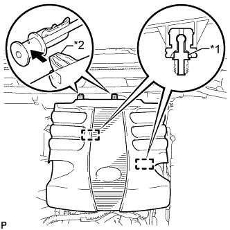
Attach the 2 V-bank cover hooks to the bracket. Then align the 2 V-bank cover grommets with the 2 pins and press down on the V-bank cover to attach the pins.
Table 10. Text in Illustration *1 Pin *2 Hook
-
- Click here
INSPECT FOR EXHAUST GAS LEAK
-
If gas is leaking, tighten the areas necessary to stop the leak. Replace damaged parts as necessary.
-
- Click here
INSTALL FRONT FENDER APRON TRIM PACKING B
-
w/ KDSS:
Install the front fender apron trim packing B with the 3 clips.
-
w/o KDSS:
Install the front fender apron trim packing B with the 4 clips.
-
- Click here
INSTALL FRONT FENDER APRON TRIM PACKING A
-
Install the front fender apron trim packing A with the 3 clips.
-
- Click here
INSTALL FRONT FENDER APRON TRIM PACKING D
-
Install the front fender apron trim packing D with the 4 clips.
-
- Click here
INSTALL FRONT FENDER APRON TRIM PACKING C
-
Install the front fender apron trim packing C with the 4 clips.
-