EXHAUST FUEL ADDITION INJECTOR (for DPF) INSTALLATION

Note
-
When replacing an injector (including interchanging injectors between cylinders) or common rail, replace the corresponding injection pipes with new ones.
-
When fuel lines are disconnected, air may enter the fuel lines, leading to engine starting trouble. Therefore, perform forced regeneration and bleed the air from the fuel lines Click here.
-
INSTALL FUEL INJECTOR SEAL
-
Install 2 new fuel injector seals.
-
-
INSTALL EXHAUST FUEL ADDITION INJECTOR ASSEMBLY
Note
If there is foreign matter on the installation surface of the exhaust fuel addition injector, be sure to clean it before installation.
-
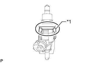
Text in Illustration *1 Nozzle Holder Clamp Install 2 new gaskets, the 2 exhaust fuel addition injectors, 2 nozzle holder clamps and 2 new washers with the 2 bolts.
- Torque:
- 28 N*m { 286 kgf*cm, 21 ft.*lbf }
Tech Tips
Align the nozzle holder clamp with the cutouts of the injector as shown in the illustration.
-
-
CONNECT FUEL TUBE SUB-ASSEMBLY
-
Connect the 2 fuel tube connectors to the exhaust fuel addition injector.
-
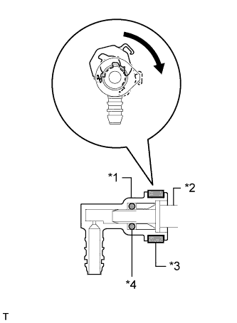
Text in Illustration *1 Fuel Tube Connector *2 Exhaust Fuel Addition Injector *3 Retainer *4 O-Ring Turn the 2 retainers in the direction indicated by the arrow until they make a "click" sound.
Note
-
If the fuel tube connector is not inserted to the correct position on the injector, the retainer cannot be turned far enough in the direction of the arrow.
-
Before connecting the fuel tube connector and fuel pipe, check that there is no damage or foreign matter on the connecting part of the fuel pipe.
-
After connecting the fuel tube connector and fuel pipe, check that they are securely connected by trying to pull them apart.
-
-
-
INSTALL NO. 1 FUEL INJECTOR PROTECTOR
-
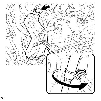
Install the No. 1 fuel injector protector with the bolt.
- Torque:
- 10 N*m { 102 kgf*cm, 7 ft.*lbf }
Tech Tips
Press the ventilation hose clip against the No. 1 fuel injector protector as shown in the illustration.
-
-
INSTALL CYLINDER HEAD COVER SILENCER RH
-
Install the cylinder head cover silencer with the 4 bolts.
- Torque:
- 5.0 N*m { 51 kgf*cm, 44 in.*lbf }
-
-
INSTALL NO. 2 FUEL INJECTOR PROTECTOR
-
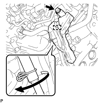
Install the No. 2 fuel injector protector with the bolt.
- Torque:
- 10 N*m { 102 kgf*cm, 7 ft.*lbf }
Tech Tips
Press the ventilation hose clip against the No. 2 fuel injector protector as shown in the illustration.
-
Attach the hose clamp.
-
-
INSTALL CYLINDER HEAD COVER SILENCER LH
-
Install the cylinder head cover silencer with the 4 bolts.
- Torque:
- 5.0 N*m { 51 kgf*cm, 44 in.*lbf }
-
-
INSTALL NO. 1 VACUUM TRANSMITTING PIPE SUB-ASSEMBLY
-
Install the vacuum transmitting pipe with the 3 bolts.
- Torque:
- 6.0 N*m { 61 kgf*cm, 53 in.*lbf }
-
Connect the 2 vacuum hoses.
-
-
INSTALL NO. 1 VACUUM SWITCHING VALVE ASSEMBLY
-
Install the vacuum switching valve with the bolt.
- Torque:
- 6.0 N*m { 61 kgf*cm, 53 in.*lbf }
-
Connect the 2 vacuum hoses.
-
-
CONNECT ENGINE WIRE
-
LH Side:
-
Install the engine wire protector with the 2 bolts.
-
Connect the 8 connectors.
-
Attach the wire harness clamp.
-
Install the engine wire harness bracket with the bolt.
-
for RHD:
Connect the wire harness with the wire harness clamp holder.
-
Attach the 3 wire harness clamps and connect the 2 connectors.
-
Attach the 3 wire harness clamps and connect the 4 connectors.
-
-
RH Side:
-
Install the engine wire harness protector with the 3 bolts.
-
Connect the 7 connectors.
-
Attach the wire harness clamp.
-
Install the wire harness bracket with the bolt.
-
Install the glow plug wire harness with the nut and screw grommet.
- Torque:
- 4.0 N*m { 41 kgf*cm, 35 in.*lbf }
-
for RHD:
Install the wire harness clamp holder with the bolt.
-
for RHD:
Connect the wire harness with the wire harness clamp holder.
-
-
Rear Side:
-
Install the glow plug wire harness with the nut and screw grommet.
- Torque:
- 4.0 N*m { 41 kgf*cm, 35 in.*lbf }
-
w/ DPF:
Connect the 3 connectors.
-
w/o DPF:
Connect the connector.
-
Install the engine wire harness protector with the 2 bolts.
-
Install the 2 ground wires with the 2 bolts.
- Torque:
- 8.4 N*m { 87 kgf*cm, 74 in.*lbf }
-
Attach the wire harness clamp.
-
-
-
INSTALL NO. 3 WATER BY-PASS PIPE (w/o Viscous Heater)
-
Connect the 2 water hose ends, and install the No. 3 water by-pass pipe with the 2 bolts.
- Torque:
- 10 N*m { 102 kgf*cm, 7 ft.*lbf }
-
-
CONNECT FUEL HOSE
-
INSTALL NO. 1 AIR CLEANER PIPE SUB-ASSEMBLY
-
Connect the No. 1 air cleaner pipe to the No. 1 intake air connector pipe.
-
Install the pipe with the bolt.
- Torque:
- 21 N*m { 214 kgf*cm, 15 ft.*lbf }
-
Tighten the hose clamp.
- Torque:
- 6.3 N*m { 64 kgf*cm, 56 in.*lbf }
-
-
INSTALL HEATER WATER PIPE SUB-ASSEMBLY (w/ Viscous Heater)
-
Connect the 4 water hose ends, and install the water pipe with the 4 bolts.
- Torque:
- 9.8 N*m { 100 kgf*cm, 87 in.*lbf }
-
-
INSTALL NO. 2 AIR CLEANER PIPE SUB-ASSEMBLY
-
Connect the No. 2 air cleaner pipe to the No. 2 intake air connector pipe.
-
Connect the ventilation hose to the oil separator.
-
Install the pipe with the bolt.
- Torque:
- 21 N*m { 214 kgf*cm, 15 ft.*lbf }
-
Tighten the hose clamp.
- Torque:
- 6.3 N*m { 64 kgf*cm, 56 in.*lbf }
-
-
INSTALL NO. 4 AIR TUBE
-
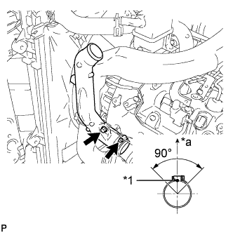
Text in Illustration *1 Paint Mark *a Top Install the No. 4 air tube with the bolt.
- Torque:
- 21 N*m { 214 kgf*cm, 15 ft.*lbf }
-
Tighten the hose clamp.
- Torque:
- 6.3 N*m { 64 kgf*cm, 56 in.*lbf }
Tech Tips
Make sure the direction of the hose clamp is as shown in the illustration.
-
Install the suction hose with the bolt.
- Torque:
- 9.8 N*m { 100 kgf*cm, 87 in.*lbf }
-
-
INSTALL NO. 2 AIR HOSE
-

Text in Illustration *1 Protrusion *2 Paint Mark *a Top Connect the No. 2 air hose with the hose clamp.
- Torque:
- 6.3 N*m { 64 kgf*cm, 56 in.*lbf }
Tech Tips
-
Align the paint mark of the air hose with the protrusion and push on the air hose so that distance B is 0 to 3 mm (0 to 0.118 in.).
-
Position the clamp so that distance A is 2 to 6 mm (0.0787 to 0.236 in.).
-
Make sure the direction of the hose clamp is as shown in the illustration.
-
-
INSTALL NO. 3 AIR TUBE
-

Text in Illustration *1 Paint Mark *a Top Install the No. 3 air tube with the bolt.
- Torque:
- 21 N*m { 214 kgf*cm, 15 ft.*lbf }
-
Tighten the hose clamp.
- Torque:
- 6.3 N*m { 64 kgf*cm, 56 in.*lbf }
Tech Tips
Make sure the direction of the hose clamp is as shown in the illustration.
-
Install the wire harness bracket with the bolt.
-
Install the ground wire with the nut, and attach the wire harness clamp.
- Torque:
- 8.4 N*m { 85 kgf*cm, 74 in.*lbf }
-
-
INSTALL NO. 1 AIR HOSE
-

Text in Illustration *1 Protrusion *2 Paint Mark *a Top Connect the No. 1 air hose with the hose clamp.
- Torque:
- 6.3 N*m { 64 kgf*cm, 56 in.*lbf }
Tech Tips
-
Align the paint mark of the air hose with the protrusion and push on the air hose so that distance B is 0 to 3 mm (0 to 0.118 in.).
-
Position the clamp so that distance A is 2 to 6 mm (0.0787 to 0.236 in.).
-
Make sure the direction of the hose clamp is as shown in the illustration.
-
-
INSTALL INTAKE AIR CONNECTOR
-
Connect the intake air connector to the No. 1 and No. 2 air cleaner pipes.
-
Install the connector with the 2 bolts.
- Torque:
- 21 N*m { 214 kgf*cm, 15 ft.*lbf }
-
Tighten the 2 hose clamps.
- Torque:
- 6.3 N*m { 64 kgf*cm, 56 in.*lbf }
-
Attach the 3 wire harness clamps.
-
w/o Viscous Heater:
Connect the connector to the water temperature sensor.
-
w/ Viscous Heater:
Connect the 2 connectors to the water temperature sensor and viscous with magnet clutch heater.
-
-
TEMPORARILY INSTALL NO. 1 AIR CLEANER HOSE
-
Temporarily install the air cleaner hose to the intake air connector.
-
-
INSTALL AIR CLEANER CAP SUB-ASSEMBLY
-
Connect the air cleaner cap to the air cleaner hose, and install the air cleaner cap with the 4 clamps.
-
Connect the mass air flow meter connector and attach the wire harness clamp to the air cleaner cap.
-
Attach the wire harness clamp.
-
Align the protrusion of the air cleaner cap and the concave portion of the air cleaner hose.
-
Tighten the 2 hose clamps.
- Torque:
- 2.5 N*m { 25 kgf*cm, 22 in.*lbf }
-
-
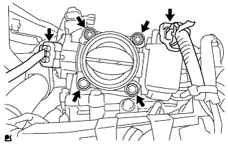
INSTALL DIESEL THROTTLE BODY ASSEMBLY LH
-
Install a new gasket to the intake pipe.
-
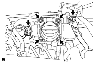
Install the throttle body with the 2 bolts and 2 nuts.
- Torque:
- 21 N*m { 214 kgf*cm, 15 ft.*lbf }
-
Connect the throttle position sensor connector.
-
Connect the throttle motor connector.
-
-
INSTALL NO. 3 INTERCOOLER SUPPORT BRACKET
-
Install the No. 3 intercooler support bracket with the 2 bolts.
- Torque:
- 21 N*m { 214 kgf*cm, 15 ft.*lbf }
-

for Manual Transmission:
-
Connect the clutch tube to release cylinder 2 way with the bolt.
- Torque:
- 20 N*m { 204 kgf*cm, 15 ft.*lbf }
-
Check that the union nut is tightened to the specified torque.
- Torque:
- 15 N*m { 154 kgf*cm, 11 ft.*lbf }
Tech Tips
Use the formula to calculate special torque values for situations where a union nut wrench is combined with a torque wrench Click here.
-
-
-
INSTALL NO. 1 GAS FILTER
-
Install the No. 1 gas filter.
-
Connect the hose to the intake pipe.
-
-
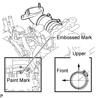
INSTALL AIR TUBE SUB-ASSEMBLY LH
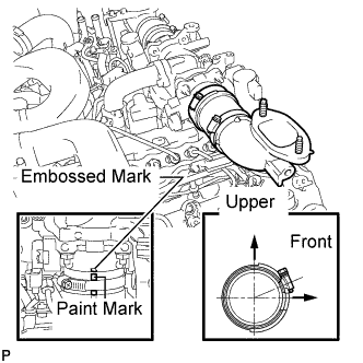
-
Install the air tube to the throttle body.
-
Align the embossed mark of the throttle body with the paint mark of the No. 4 air hose.
-
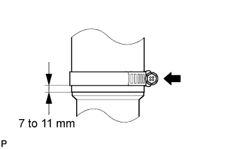
Tighten the hose clamp so that it is 7 to 11 mm (0.276 to 0.433 in.) from the end of the hose as shown in the illustration.
- Torque:
- 6.3 N*m { 64 kgf*cm, 56 in.*lbf }
-
-
INSTALL DIESEL THROTTLE BODY ASSEMBLY RH
-
Install a new gasket to the intake pipe.
-
Install the throttle body with the 2 bolts and 2 nuts.
- Torque:
- 21 N*m { 214 kgf*cm, 15 ft.*lbf }
-
Connect the throttle position sensor connector.
-
Connect the throttle motor connector.
-
-
INSTALL AIR TUBE SUB-ASSEMBLY RH
-
Install the air tube to the throttle body.
-
Align the embossed mark of the throttle body with the paint mark of the No. 4 air hose.
-
Tighten the hose clamp so that it is 7 to 11 mm (0.276 to 0.433 in.) from the end of the hose as shown in the illustration.
- Torque:
- 6.3 N*m { 64 kgf*cm, 56 in.*lbf }
-
-
INSTALL NO. 2 ENGINE OIL LEVEL DIPSTICK GUIDE
-
Apply a light coat of engine oil to a new O-ring.
-
Install the O-ring to the No. 2 engine oil level dipstick guide.
-
Install the No. 2 engine oil level dipstick guide with the 2 bolts.
- Torque:
- 10 N*m { 102 kgf*cm, 7 ft.*lbf }
-
Connect the ventilation hose to the cylinder head cover RH.
-
Connect the wire harness clamp to the No. 2 engine oil level dipstick guide bracket.
-
-
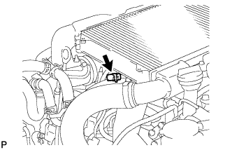
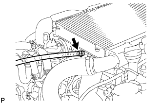
CONNECT WATER HOSE SUB-ASSEMBLY
-
INSTALL INTERCOOLER ASSEMBLY
-
CONNECT CABLE TO NEGATIVE BATTERY TERMINAL
Note
When disconnecting the cable, some systems need to be initialized after the cable is reconnected Click here.
-
ADD ENGINE COOLANT
-
Remove the engine air bleed cap.
-
Connect a clear hose to the engine air bleed pipe.
-
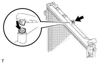
Using a wrench, remove the vent plug.
-
Fill the radiator with TOYOTA SLLC to the radiator reservoir filler neck.
Tech Tips
Pour TOYOTA SLLC until it spills out of the engine air bleed pipe.
Standard Capacity (for Automatic Transmission) Item Specified Condition Front heater only 14.8 liters (15.6 US qts, 13.0 Imp. qts) Front heater and rear heater 17.6 liters (18.6 US qts, 15.5 Imp. qts) Front heater with viscous heater 15.2 liters (16.1 US qts, 13.4 Imp. qts) Front heater and rear heater with viscous heater 18.0 liters (19.0 US qts, 15.4 Imp. qts) Standard capacity (for Manual Transmission) 15.4 liters (16.3 US qts, 13.5 Imp. qts) Note
Do not substitute plain water for engine coolant.
Tech Tips
TOYOTA vehicles are filled with TOYOTA SLLC at the factory. In order to avoid damage to the engine cooling system and other technical problems, only use TOYOTA SLLC or similar high quality ethylene glycol based non-silicate, non-amine, non-nitrite, non-borate coolant with long-life hybrid organic acid technology (coolant with long-life hybrid organic acid technology consists of a combination of low phosphates and organic acids).
-
Install the vent plug.
- Torque:
- 2.0 N*m { 20 kgf*cm, 18 in.*lbf }
Note
Do not tighten the plug to 5.0 N*m (51 kgf*cm, 44 in.*lbf) or more, as the plug will be damaged.
-
Disconnect the clear hose from the engine air bleed pipe.
-
Install the engine air bleed cap when coolant comes out.
-
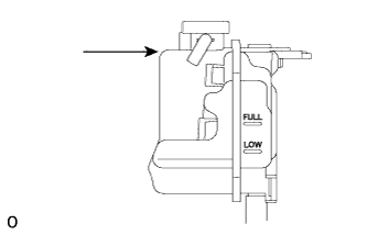
Install the radiator reservoir cap.
-
Start the engine.
Note
Immediately after starting the engine, if the radiator reservoir does not have any coolant, perform the following: 1) stop the engine, 2) wait until the coolant has cooled down, and 3) add coolant until the coolant is filled to the FULL line.
-
Maintain an engine speed of 3000 rpm for approximately 10 minutes so that the thermostat opens and air bleeding is performed.
CAUTION:
-
Wear protective gloves.
-
Be careful as the radiator hoses are hot.
-
Keep your hands away from the radiator fan
When pressing the radiator hoses:
Note
-
Pay attention to the needle of the water temperature meter. Make sure that the needle does not show an abnormally high temperature.
-
If there is not enough coolant, the engine may burn out or overheat.
Tech Tips
The thermostat opening timing can be confirmed by pressing the No. 2 radiator hose by hand, and checking when the engine coolant starts to flow inside the hose.
-
-
Stop the engine, and wait until the engine coolant cools down to ambient temperature.
CAUTION:
Do not remove the radiator reservoir cap while the engine and radiator are still hot. Pressurized, hot engine coolant and steam may be released and cause serious burns.
-
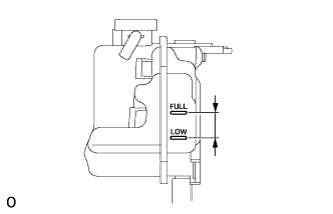
Check that the coolant level is between the FULL and LOW lines.
If the coolant level is above the FULL line, drain coolant so that the coolant level is between the FULL and LOW lines.
-
-
BLEED AIR FROM FUEL SYSTEM
-

Using the hand pump mounted on the fuel filter cap, bleed air from the fuel system. Continue pumping until the pump resistance increases.
Note
-
The maximum hand pump pumping speed is 2 strokes per second.
-
The hand pump must be pushed with a full stroke during pumping.
-
When the fuel pressure at the supply pump inlet port reaches a saturated pressure, the hand pump resistance increases.
-
If pumping is interrupted during the air bleeding process, fuel in the fuel line may return to the fuel tank. Continue pumping until the hand pump resistance increases.
-
If the hand pump resistance does not increase despite consecutively pumping 200 times or more, there may be a fuel leak between the fuel tank and fuel filter, the hand pump may be malfunctioning, or the vehicle may have run out of fuel.
-
If air bleeding using the hand pump is incomplete, the common rail pressure does not rise to the pressure range necessary for normal use and the engine cannot be started.
-
-
Check if the engine starts.
Note
-
Even if air bleeding using the hand pump has been completed, the starter may need to be cranked for 10 seconds or more to start the engine.
-
Do not crank the engine continuously for more than 20 seconds. The battery may be discharged.
-
Use a fully-charged battery.
-
When the engine can be started, proceed to the next step.
-
If the engine cannot be started, bleed air again using the hand pump until the hand pump resistance increases (refer to the procedures above). Then start the engine.
-
-
Turn the engine switch off.
-
Connect the GTS to the DLC3.
-
Turn the engine switch ON (IG) and turn the GTS on.
-
Clear the DTCs Click here.
-
Start the engine.*1
-
Enter the following menus: Powertrain / Engine and ECT / Active Test / Test the Fuel Leak.*2
-
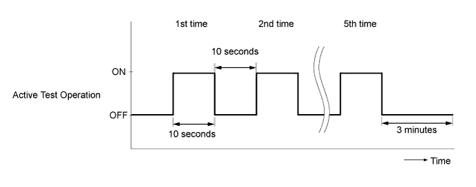
Perform the following test 5 times with on/off intervals of 10 seconds: Active Test / Test the Fuel Leak.*3
-
Allow the engine to idle for 3 minutes or more after performing the Active Test for the 5th time.
Tech Tips
When the Active Test "Test the Fuel Leak" is used to change the pump control mode, the actual fuel pressure inside the common rail drops below the target fuel pressure when the Active Test is off, but this is normal and does not indicate a pump malfunction.
-
Enter the following menus: Powertrain / Engine and ECT / Trouble Codes.
-
Read Current DTCs.
-
Clear the DTCs Click here.
Tech Tips
It is necessary to clear the DTCs as DTC P1604 or P1605 may be stored when air is bled from the fuel system after replacing or repairing fuel system parts.
-
Repeat steps *1 to *3.
-
Enter the following menus: Powertrain / Engine and ECT / Trouble Codes.
-
Read Current DTCs.
OK No DTCs are output.
-
-
PERFORM DPF FORCIBLE REGENERATION PROCEDURE
-
INSPECT FOR COOLANT LEAK
CAUTION:
Do not remove the radiator reservoir cap while the engine and radiator are still hot. Pressurized, hot engine coolant and steam may be released and cause serious burns.
-
Fill the radiator with coolant and attach a radiator cap tester to the radiator reservoir.
-
Warm up the engine.
-
Using the radiator cap tester, increase the pressure inside the radiator to 123 kPa (1.3 kgf/cm2, 17.8 psi), and check that the pressure does not drop.
If the pressure drops, check the hoses, radiator and water pump for leaks.
If no external leaks are found, check the cylinder block and cylinder head.
-
-
INSPECT FOR FUEL LEAK
-
Perform the Active Test.
-
Connect the GTS to the DLC3.
-
Turn the engine switch to ON (IG).
-
Start the engine.
-
Turn the GTS on.
-
Enter the following menus: Powertrain / Engine and ECT / Active Test.
-
Perform the Active Test.
Tester Display Test Detail Control Range Diagnostic Note Test the Fuel Leak Pressurizes fuel inside common rail and checks for fuel leaks Stop/Start
-
The fuel inside the common rail is pressurized to the specified value and the engine speed increases to 2000 rpm when Start is selected.
-
The above conditions are preserved while Start is selected.
-
-
-
-
INSPECT FOR OIL LEAK
-
Warm up the engine and check for an engine oil leak.
-
-
INSTALL UPPER RADIATOR SUPPORT SEAL
-
Install the upper radiator support seal with the 7 clips.
-
-
INSTALL NO. 1 ENGINE UNDER COVER SUB-ASSEMBLY
-
Install the No. 1 engine under cover with the 10 bolts.
- Torque:
- 29 N*m { 296 kgf*cm, 21 ft.*lbf }
-
-
INSTALL FRONT FENDER SPLASH SHIELD SUB-ASSEMBLY RH
-
Install the front fender splash shield RH with the clip, and then install the 3 bolts and 2 screws.
-
-
INSTALL FRONT FENDER SPLASH SHIELD SUB-ASSEMBLY LH
-
Install the front fender splash shield LH with the clip, and then install the 3 bolts and screw.
-