- Click here
DISCHARGE FUEL SYSTEM PRESSURE
- Click here
PRECAUTION
Note:After turning the engine switch off, waiting time may be required before disconnecting the cable from the battery terminal. Therefore, make sure to read the disconnecting the cable from the battery terminal notice before proceeding with work (Click here).
- Click here
DISCONNECT CABLE FROM NEGATIVE BATTERY TERMINAL
Note:When disconnecting the cable, some systems need to be initialized after the cable is reconnected (Click here).
- Click here
REMOVE V-BANK COVER SUB-ASSEMBLY
-
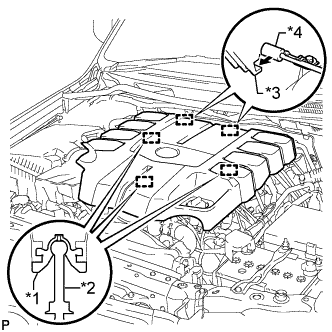
Raise the front of the V-bank cover to detach the 3 pins. Then remove the 2 V-bank cover hooks from the bracket, and remove the V-bank cover.
Table 1. Text in Illustration *1 Grommet *2 Pin *3 Hook *4 Bracket
-
- Click here
REMOVE AIR CLEANER CAP AND HOSE
-
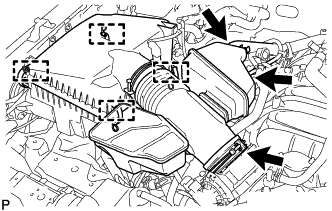
Disconnect the No. 2 PCV hose and No. 1 air hose.
-
Disconnect the mass air flow meter connector and detach the clamp.
-
Detach the 4 clamps.
-
Loosen the hose clamp and remove the air cleaner cap and hose.
-
- Click here
REMOVE FRONT FENDER SPLASH SHIELD SUB-ASSEMBLY LH
-
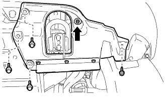
Remove the 3 bolts and screw.
-
Turn the clip indicated by the arrow in the illustration to remove the front fender splash shield sub-assembly LH.
-
- Click here
REMOVE FRONT FENDER SPLASH SHIELD SUB-ASSEMBLY RH
-
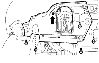
Remove the 3 bolts and 2 screws.
-
Turn the clip indicated by the arrow in the illustration to remove the front fender splash shield sub-assembly RH.
-
- Click here
REMOVE NO. 1 ENGINE UNDER COVER SUB-ASSEMBLY
-
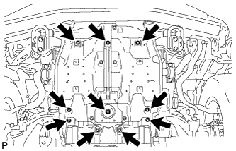
Remove the 10 bolts and No. 1 engine under cover sub-assembly.
-
- Click here
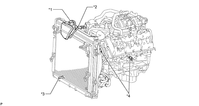
DRAIN ENGINE COOLANT
CAUTION:Do not remove the radiator cap while the engine and radiator are still hot. Pressurized, hot engine coolant and steam may be released and cause serious burns.
-
Loosen the radiator drain cock plug.
-
Remove the radiator cap and drain the coolant.
Tip:Collect the coolant in a container and dispose of it according to the regulations in your area.
-
Loosen the 2 cylinder block drain cock plugs and drain the coolant from the engine.
-
Tighten the 2 cylinder block drain cock plugs.
13 N*m 130 kgf*cm 9 ft.*lbf -
Tighten the radiator drain cock plug by hand.
Table 2. Text in Illustration *1 Reservoir Cap *2 Radiator Cap *3 Radiator Drain Cock Plug *4 Cylinder Block Drain Cock Plug
-
- Click here
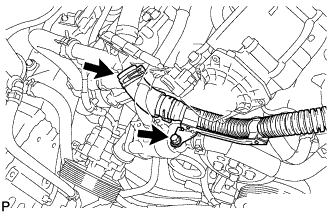
REMOVE NO. 5 WATER BY-PASS PIPE
-
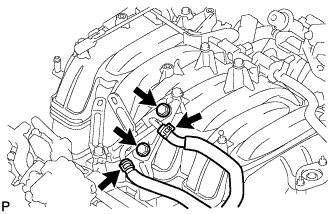
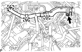
Disconnect the 2 water by-pass hoses and remove the 2 bolts and No. 5 water by-pass pipe.
-
- Click here
REMOVE EGR VALVE BRACKET
-
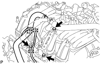
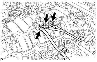
Detach the 2 wire harness clamps and PCV hose clamp.
-
Remove the 3 bolts and EGR valve bracket.
-
- Click here
REMOVE PCV HOSE ASSEMBLY
-
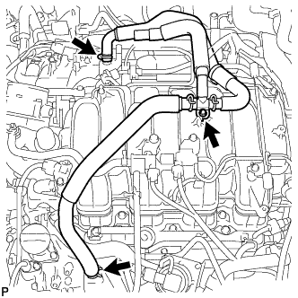
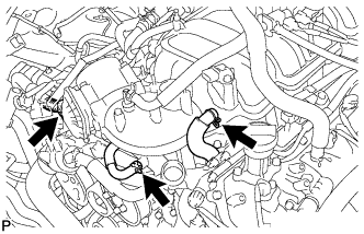
Disconnect the PCV hose from the PCV pipe of the cylinder head cover LH and RH.
-
Remove the bolt and PCV hose.
-
- Click here
REMOVE AIR TUBE SUB-ASSEMBLY (w/ Secondary Air Injection System)
-
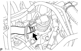
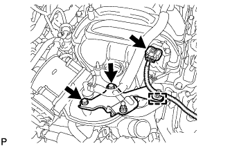
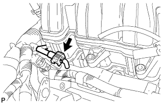
Disconnect the No. 2 air injection system hose from the air switching valve.
-
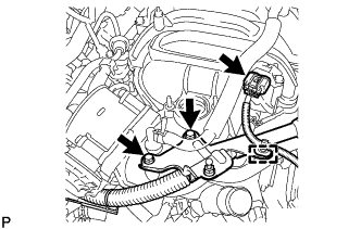
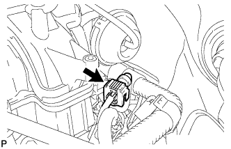
Disconnect the manifold absolute pressure sensor connector and detach the clamp.
-
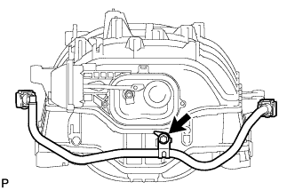
Remove the 2 bolts and bracket.
-
Remove the bolt and air tube.
-
- Click here
REMOVE INTAKE MANIFOLD
-
w/o Secondary Air Injection System:
-
Disconnect the manifold absolute pressure sensor connector and detach the clamp.
-
Remove the 2 bolts and bracket.
-
-
Disconnect the No. 4 water by-pass hose.
-
Disconnect the throttle position sensor and throttle control motor connector.
-
Disconnect the PCV valve hose.
-
Disconnect the purge VSV connector.
-
Disconnect the purge line hose from the purge VSV.
-
Disconnect the vacuum switching valve connector (for ACIS).
-
Remove the bolt.
-
Detach the 3 wire harness clamps from the 3 wire harness brackets.
-
Disconnect the fuel tube from the fuel delivery pipe (Click here).
-
Disconnect the fuel tube from the No. 2 fuel delivery pipe (Click here).
-
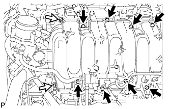
Remove the 2 nuts, 8 bolts, intake manifold and 2 gaskets.
Table 3. Text in Illustration 
Bolt 
Nut
-
- Click here
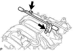
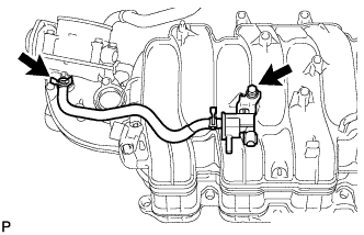
REMOVE FUEL TUBE SUB-ASSEMBLY
-
Remove the bolt and fuel tube from the intake manifold.
-
- Click here
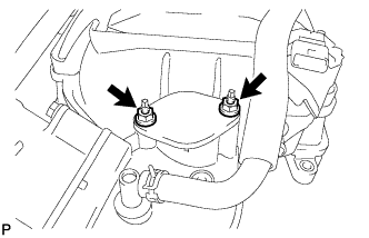
REMOVE BRACKET
-
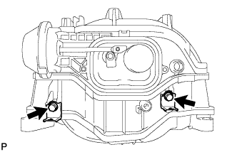
Remove the 2 bolts and 2 brackets.
-
- Click here
REMOVE V-BANK COVER BRACKET
-
Remove the 2 bolts and V-bank cover bracket.
-
- Click here
REMOVE V-BANK COVER PIN
-
Remove the V-bank cover pin from the intake manifold.
-
- Click here
REMOVE INTAKE FLANGE
-
Remove the 2 nuts and intake flange.
-
- Click here
REMOVE STUD BOLT
Note:If a stud bolt is deformed or its threads are damaged, replace it.
-
Using an E5 "TORX" socket wrench, remove the 2 stud bolts.
-
- Click here
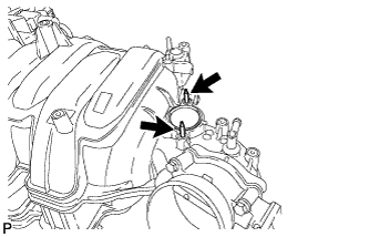
REMOVE VACUUM SWITCHING VALVE ASSEMBLY (for ACIS)
-
Disconnect the 2 vacuum hoses and detach the 3 clamps.
-
Remove the bolt and vacuum switching valve.
-
- Click here
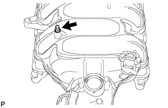
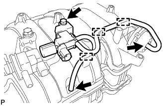
REMOVE PURGE VSV
-
Disconnect the purge line hose from the intake manifold.
-
Remove the bolt and purge VSV.
-
- Click here
REMOVE MANIFOLD ABSOLUTE PRESSURE SENSOR
-
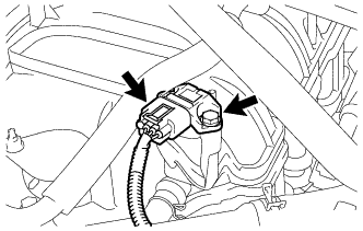
Disconnect the manifold absolute pressure sensor connector.
-
Remove the bolt and manifold absolute pressure sensor.
-
- Click here
REMOVE THROTTLE BODY WITH MOTOR ASSEMBLY
-
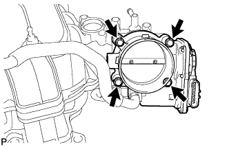
Remove the 4 bolts, throttle body with motor assembly and gasket.
-