AIR CONDITIONING SYSTEM (for Manual Air Conditioning System), Diagnostic DTC:B1422

| DTC Code | DTC Name |
|---|---|
| B1422 | Compressor Lock Sensor Circuit |
SYSTEM DESCRIPTION
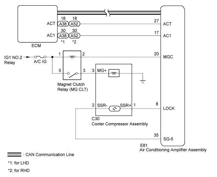
The ECM sends the engine speed signal to the air conditioning amplifier assembly via CAN communication.
The air conditioning amplifier assembly sends an air conditioning operation request signal to the ECM via direct line, and the ECM sends a magnet clutch operation permission signal to the air conditioning amplifier assembly via direct line.
The air conditioning amplifier assembly reads the difference between compressor speed and engine speed. When the difference becomes too large, the air conditioning amplifier assembly determines that the cooler compressor assembly is locked and turns the magnet clutch assembly off.
| DTC Code | DTC Detection Condition | Trouble Area |
|---|---|---|
| B1422 | An open or short in the compressor lock sensor circuit. |
|
WIRING DIAGRAM
INSPECTION PROCEDURE
Tech Tips
As DTC B1422 is also output when the fan & generator V-belt is damaged or loose, inspect the belt before performing troubleshooting.
PROCEDURE
-
CHECK CAN COMMUNICATION SYSTEM
-
Use the intelligent tester to check if the CAN communication system is functioning normally Click here.
Result Result Proceed to CAN DTC is not output A CAN DTC is output (for LHD) B CAN DTC is output (for RHD) C
B 
GO TO CAN COMMUNICATION SYSTEM Click here
C
GO TO CAN COMMUNICATION SYSTEM Click here
A 
-
-
INSPECT MAGNET CLUTCH RELAY (MG CLT)
-
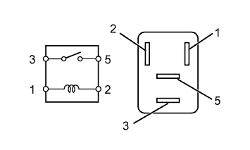
Remove the magnet clutch relay (MG CLT).
-
Measure the resistance according to the value(s) in the table below.
Standard Resistance Tester Connection Condition Specified Condition 3 - 5 Battery voltage is not applied to terminals 1 and 2 10 kΩ or higher Battery voltage is applied to terminals 1 and 2 Below 1 Ω
NG
REPLACE MAGNET CLUTCH RELAY (MG CLT)
OK
-
-
CHECK HARNESS AND CONNECTOR (MAGNET CLUTCH RELAY - BATTERY, AIR CONDITIONING AMPLIFIER AND COOLER COMPRESSOR)
-
Remove the magnet clutch relay (MG CLT).
-
Disconnect the E81 air conditioning amplifier assembly connector.
-
Disconnect the C30 cooler compressor assembly connector.
-
Measure the voltage according to the value(s) in the table below.
Standard Voltage Tester Connection Switch Condition Specified Condition Magnet clutch relay terminal 1 - Body ground Ignition switch ON 11 to 14 V Ignition switch off Below 1 V Magnet clutch relay terminal 5 - Body ground Ignition switch ON 11 to 14 V Ignition switch off Below 1 V -
Measure the resistance according to the value(s) in the table below.
Standard Resistance Tester Connection Condition Specified Condition Magnet clutch relay terminal 2 - E81-20 (MGC) Always Below 1 Ω Magnet clutch relay terminal 3 - C30-3 (MG+) Magnet clutch relay terminal 1 - Body ground Always 10 kΩ or higher Magnet clutch relay terminal 2 - Body ground Magnet clutch relay terminal 3 - Body ground Magnet clutch relay terminal 4 - Body ground
NG
REPAIR OR REPLACE HARNESS OR CONNECTOR
OK
-
-
CHECK AIR CONDITIONING AMPLIFIER ASSEMBLY
-
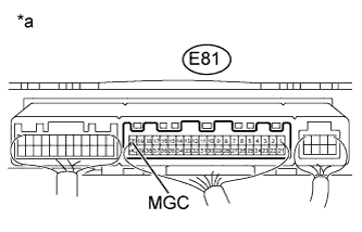
Text in Illustration *a Component with harness connected
(Air Conditioning Amplifier Assembly)
Remove the air conditioning amplifier assembly with its connectors still connected Click here.
-
Measure the voltage according to the value(s) in the table below.
Standard Voltage Tester Connection Condition Specified Condition E81-20 (MGC) - Body ground
-
Engine idling
-
Blower switch LO level
-
A/C switch on (magnet clutch on permitted)
Below 1 V
-
Engine idling
-
Blower switch LO level
-
A/C switch off or on (magnet clutch on not permitted)
11 to 14 V -
NG 
CHECK HARNESS AND CONNECTOR (AIR CONDITIONING AMPLIFIER - ECM) Click here
OK
-
-
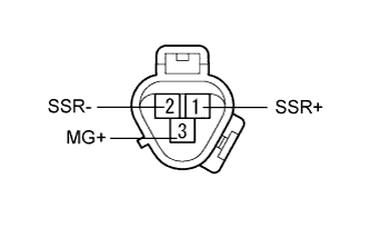
INSPECT COOLER COMPRESSOR ASSEMBLY
-
Remove the cooler compressor assembly.
-
for 1VD-FTV: Click here.
-
for 1GR-FE: Click here.
-
-
Check the magnet clutch operation.
OK Measurement Connection Specified Condition Battery positive (+) → 3 (MG+)
Battery negative (-) → cooler compressor assembly body
Magnet clutch engages -
Measure the resistance according to the value(s) in the table below.
Standard Resistance Tester Connection Condition Specified Condition 1 (SSR+) - 2 (SSR-) 20°C (68°F) 160 to 320 Ω Result Result Proceed to OK A NG (for 1VD-FTV) B NG (for 1GR-FE) C
B
REPLACE COOLER COMPRESSOR ASSEMBLY Click here
C
REPLACE COOLER COMPRESSOR ASSEMBLY Click here
A
-
-
CHECK HARNESS AND CONNECTOR (AIR CONDITIONING AMPLIFIER - COOLER COMPRESSOR)
-
Disconnect the E81 air conditioning amplifier assembly connector.
-
Disconnect the C30 cooler compressor connector.
-
Measure the resistance according to the value(s) in the table below.
Standard Resistance Tester Connection Condition Specified Condition E81-8 (LOCK) - C30-1 (SSR+) Always Below 1 Ω E81-35 (SG-5) - C30-2 (SSR-) Always Below 1 Ω E81-8 (LOCK) - Body ground Always 10 kΩ or higher E81-35 (SG-5) - Body ground Always 10 kΩ or higher Result Result Proceed to OK (When troubleshooting according to problem symptoms table) A OK (When troubleshooting according to the DTC) B NG C
B
REPLACE AIR CONDITIONING AMPLIFIER ASSEMBLY Click here
C
REPAIR OR REPLACE HARNESS OR CONNECTOR
A 
PROCEED TO NEXT SUSPECTED AREA SHOWN IN PROBLEM SYMPTOMS TABLE Click here
-
-
CHECK HARNESS AND CONNECTOR (AIR CONDITIONING AMPLIFIER - ECM)
-
Disconnect the E81 air conditioning amplifier assembly connector.
-
Disconnect the A38*1 or A52*2 ECM connector.
-
*1: for LHD
-
*2: for RHD
-
-
Measure the resistance according to the value(s) in the table below.
Standard Resistance for LHD Tester Connection Condition Specified Condition E81-17 (AC1) - A38-30 (AC1) Always Below 1 Ω E81-27 (ACT) - A38-18 (ACT) Always Below 1 Ω E81-17 (AC1) - Body ground Always 10 kΩ or higher E81-27 (ACT) - Body ground Always 10 kΩ or higher for RHD Tester Connection Condition Specified Condition E81-17 (AC1) - A52-30 (AC1) Always Below 1 Ω E81-27 (ACT) - A52-18 (ACT) Always Below 1 Ω E81-17 (AC1) - Body ground Always 10 kΩ or higher E81-27 (ACT) - Body ground Always 10 kΩ or higher
NG
REPAIR OR REPLACE HARNESS OR CONNECTOR
OK
-
-
CHECK AIR CONDITIONING AMPLIFIER ASSEMBLY
-
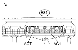
Text in Illustration *a Component with harness connected
(Air Conditioning Amplifier Assembly)
Remove the air conditioning amplifier assembly with its connectors still connected Click here.
-
Measure the voltage according to the value(s) in the table below.
Standard Voltage Tester Connection Condition Specified Condition E81-17 (AC1) - Body ground
-
Engine idling
-
Blower switch LO level
-
A/C switch on
Below 1 V
-
Engine idling
-
Blower switch LO level
-
A/C switch off
11 to 14 V E81-27 (ACT) - Body ground
-
Engine idling
-
Blower switch LO level
-
A/C switch on (magnet clutch on)
Below 1 V
-
Engine idling
-
Blower switch LO level
-
A/C switch off or on (magnet clutch off)
11 to 14 V -
NG
REPLACE AIR CONDITIONING AMPLIFIER ASSEMBLY Click here
OK
REPLACE AIR CONDITIONING AMPLIFIER ASSEMBLY Click here
-
-
REPLACE AIR CONDITIONING AMPLIFIER ASSEMBLY
-
Temporarily replace the air conditioning amplifier assembly with a new or normally functioning one Click here.
-
Check the air conditioning system to check it functions properly.
OK Air conditioning system functions operate normally. Result Result Proceed to OK A NG (for 1GR-FE) B NG (for 1VD-FTV) C
B
REPLACE ECM Click here
C
REPLACE ECM Click here
A
END (AIR CONDITIONING AMPLIFIER ASSEMBLY IS FAULTY)
-