AIR CONDITIONING SYSTEM (for Manual Air Conditioning System) SYSTEM DESCRIPTION

-
GENERAL
-
The air conditioning system has the following control.
Control Outline Diagnosis A Diagnostic Trouble Code (DTC) is stored in memory when the air conditioning amplifier assembly detects a problem with the air conditioning system.
-
-
MODE POSITION AND DAMPER OPERATION
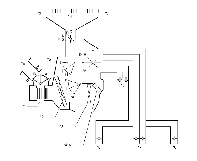
Text in Illustration *A w/ PTC Heater - - *1 Blower with Fan Motor Sub-assembly *2 No. 1 Cooler Evaporator Sub-assembly *3 Heater Radiator Unit Sub-assembly *4 Footwell Register Duct *5 Side Register *6 Center Register *7 Center Defroster *8 Side Defroster *a Fresh Air *b Recirculation Air Function of Main Damper Control Damper Operation Position Damper Position Operation Air Inlet Control Damper Fresh A Brings in fresh air. Recirculation B Recirculates internal air. Air Mix Control Damper Max Cool to Max Hot K, L, M Varies the mixture ratio of cold air and hot air in order to regulate the temperature continuously from hot to cool. Cool Air Bypass Control Damper Max Cool to Max Hot H, I, J Cool air blows out from the front center register and side registers in order to adjust the temperature around the heads of the occupants during cooling or warming. Mode Control Damper 
Def
C Defrosts the windshield through the center defroster and side defrosters. 
Foot/Def
D Defrosts the windshield through the center defroster and side defrosters while air is also blown out from the footwell register duct.
In addition, air blows out slightly from the center register and side registers.

Foot
E Air blows out of the footwell register ducts, center register and side registers.
In addition, air blows out slightly from the center defroster and side defrosters.

Bi-Level
F Air blows out of the center register and side registers.
Air also blows out from the footwell register ducts.

Face
G Air blows out of the center register and side registers. -
AIR OUTLETS AND AIRFLOW VOLUME
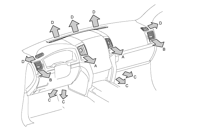
Air Outlet Mode Center Side Foot Defroster A B C D FACE 
- - B/L 

- FOOT 
F/D DEF - - - Tech Tips
The size of the circle indicates the proportion of airflow volume.