AIR CONDITIONING SYSTEM (for Automatic Air Conditioning System) Rear Air Conditioning Relay Circuit
DESCRIPTION
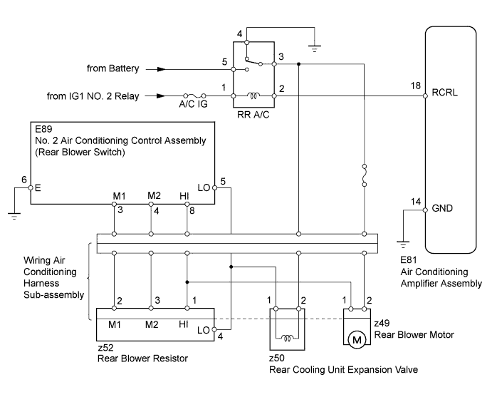
When the No. 2 air conditioning control assembly (rear blower switch) is set to position LO or higher, the contact of the RR A/C relay is closed, current flows to the rear blower motor, and the rear blower motor operates. The rear blower motor speed can be changed by exchanging the ground and the rear blower resistor circuit with the No. 2 air conditioning control assembly (rear blower switch).
WIRING DIAGRAM
INSPECTION PROCEDURE
PROCEDURE
-
INSPECT FUSE (A/C IG, RR A/C NO.2)
-
Remove the A/C IG and RR A/C NO. 2 fuses from the cowl side junction block LH.
-
Measure the resistance according to the value(s) in the table below.
Standard Resistance Tester Connection Condition Specified Condition A/C IG fuse Always Below 1 Ω RR A/C NO. 2 fuse Always Below 1 Ω
NG 
REPLACE FUSE
OK 
-
-
INSPECT RR A/C RELAY
-
Remove the RR A/C relay from the engine room relay block.
-
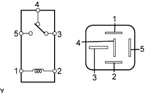
Measure the resistance according to the value(s) in the table below.
Standard Resistance Tester Connection Condition Specified Condition 3 - 4 Battery voltage is not applied between terminals 1 and 2 Below 1 Ω 3 - 5 Battery voltage is not applied between terminals 1 and 2 10 kΩ or higher 3 - 4 Battery voltage is applied to terminals 1 and 2 10 kΩ or higher 3 - 5 Battery voltage is applied to terminals 1 and 2 Below 1 Ω
NG
REPLACE RR A/C RELAY
OK
-
-
INSPECT REAR BLOWER MOTOR
-
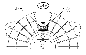
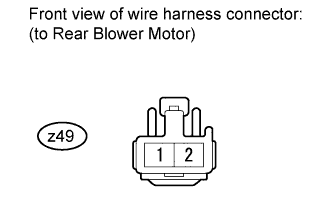
Disconnect the z49 motor connector.
-
Connect the battery's positive (+) lead to terminal 2 and the negative (-) lead to terminal 1, then check that the rear blower motor operates smoothly.
OK The rear blower motor operates smoothly. -
Measure the current according to the value(s) in the table below.
Standard Current Tester Connection Condition Specified Condition z49-1 (-) - z49-2 (+) Rear blower motor operates 1 to 3 A
NG
REPLACE REAR BLOWER MOTOR Click here
OK
-
-
INSPECT NO. 2 AIR CONDITIONING CONTROL ASSEMBLY (REAR BLOWER SWITCH)
-
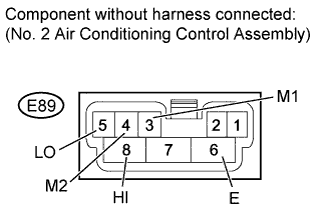
Remove the No. 2 air conditioning control assembly Click here.
-
Measure the resistance according to the value(s) in the table below.
Standard Resistance Tester Connection Switch Condition Specified Condition ALL - E89-6 (E) OFF 10 kΩ or higher E89-5 (LO) - E89-6 (E) LO Below 1 Ω E89-3 (M1) - E89-6 (E) M1 Below 1 Ω E89-4 (M2) - E89-6 (E) M2 Below 1 Ω E89-8 (HI) - E89-6 (E) HI Below 1 Ω
NG
REPLACE NO. 2 AIR CONDITIONING CONTROL ASSEMBLY Click here
OK
-
-
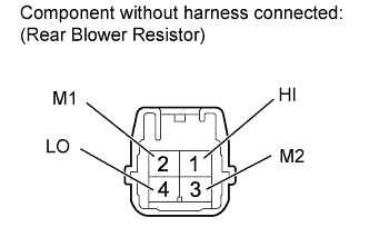
INSPECT REAR BLOWER RESISTOR
-
Remove the rear blower resistor Click here.
-
Measure the resistance according to the value(s) in the table below.
Standard Resistance Tester Connection Condition Specified Condition z52-1 (HI) - z52-2 (M1) Always 1.32 to 1.52 Ω z52-1 (HI) - z52-3 (M2) Always 0.39 to 0.45 Ω z52-1 (HI) - z52-4 (LO) Always 2.24 to 2.4 Ω
NG
REPLACE REAR BLOWER RESISTOR Click here
OK
-
-
CHECK REAR COOLING UNIT EXPANSION VALVE (OPERATION)
-
Replace the rear cooling unit expansion valve Click here.
Tech Tips
Since the rear cooling unit expansion valve cannot be inspected while it is removed from the vehicle, replace the rear cooling unit expansion valve with a normal one and check that the condition returns to normal.
OK Same problem does not occur.
NG 
CHECK HARNESS AND CONNECTOR (REAR BLOWER RESISTOR - WIRING AIR CONDITIONING HARNESS) Click here
OK 
CHECK REAR COOLING UNIT EXPANSION VALVE Click here
-
-
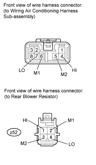
CHECK HARNESS AND CONNECTOR (REAR BLOWER RESISTOR - WIRING AIR CONDITIONING HARNESS)
-
Disconnect the wiring air conditioning harness sub-assembly connector.
-
Disconnect the z52 rear blower resistor connector.
-
Measure the resistance according to the value(s) in the table below.
Standard Resistance Tester Connection Condition Specified Condition 6 (M1) - z52-2 (M1) Always Below 1 Ω 5 (M2) - z52-3 (M2) Always Below 1 Ω 4 (HI) - z52-1 (HI) Always Below 1 Ω 7 (LO) - z52-4 (LO) Always Below 1 Ω
NG
REPAIR OR REPLACE HARNESS OR CONNECTOR
OK
-
-
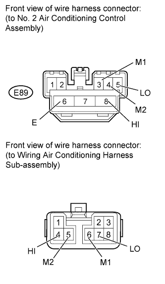
CHECK HARNESS AND CONNECTOR (REAR BLOWER SWITCH - WIRING AIR CONDITIONING HARNESS)
-
Disconnect the E89 No. 2 air conditioning control assembly connector.
-
Disconnect the Wiring air conditioning harness sub-assembly connector.
-
Measure the resistance according to the value(s) in the table below.
Standard Resistance Tester Connection Condition Specified Condition E89-3 (M1) - 6 (M1) Always Below 1 Ω E89-4 (M2) - 5 (M2) Always Below 1 Ω E89-8 (HI) - 4 (HI) Always Below 1 Ω E89-5 (LO) - 7 (LO) Always Below 1 Ω E89-6 (E) - Body ground Always Below 1 Ω
NG
REPAIR OR REPLACE HARNESS OR CONNECTOR
OK
-
-
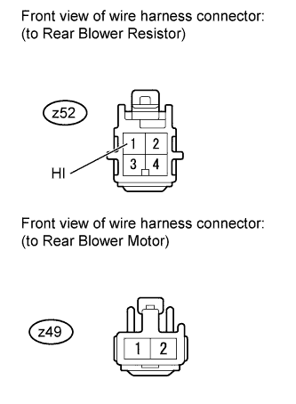
CHECK HARNESS AND CONNECTOR (REAR BLOWER RESISTOR - REAR BLOWER MOTOR)
-
Disconnect the z52 rear blower resistor connector.
-
Disconnect the z49 rear motor connector.
-
Measure the resistance according to the value(s) in the table below.
Standard Resistance Tester Connection Condition Specified Condition z52-1 (HI) - z49-1 Always Below 1 Ω
NG
REPAIR OR REPLACE HARNESS OR CONNECTOR
OK
-
-
CHECK HARNESS AND CONNECTOR (REAR BLOWER MOTOR - BODY GROUND AND BATTERY)
-
Disconnect the z49 rear motor connector.
-
Measure the resistance according to the value(s) in the table below.
Standard Resistance Tester Connection Condition Specified Condition z49-2 - Body ground Always Below 1 Ω -
Measure the voltage according to the value(s) in the table below.
Standard Voltage Tester Connection Switch Condition Specified Condition z49-2 - Body ground Engine switch on (IG)
Heater control (blower switch) HI
11 to 14 V
NG
REPAIR OR REPLACE HARNESS OR CONNECTOR
OK
-
-
CHECK HARNESS AND CONNECTOR (AIR CONDITIONING AMPLIFIER - BATTERY AND BODY GROUND)
-
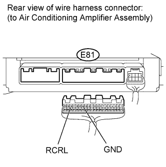
Disconnect the E81air conditioning amplifier connector.
-
Measure the voltage according to the value(s) in the table below.
Standard Voltage Tester Connection Switch Condition Specified Condition E81-18 (RCRL) - Body ground Engine switch on (IG)
Heater control (blower switch): OFF
11 to 14 V E81-18 (RCRL) - Body ground Engine switch on (IG)
Heater control (blower switch): ON
Below 1 V -
Measure the resistance according to the value(s) in the table below.
Standard Resistance Tester Connection Condition Specified Condition E81-14 (GND) - Body ground Always Below 1 Ω
NG
REPAIR OR REPLACE HARNESS OR CONNECTOR
OK
PROCEED TO NEXT CIRCUIT INSPECTION SHOWN IN PROBLEM SYMPTOMS TABLE Click here
-