AIR CONDITIONING SYSTEM (for Automatic Air Conditioning System) Heater Control Switch Circuit
DESCRIPTION
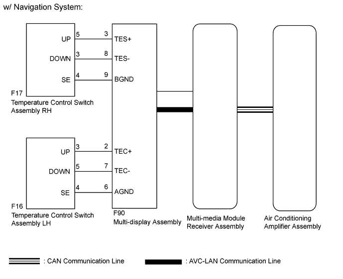
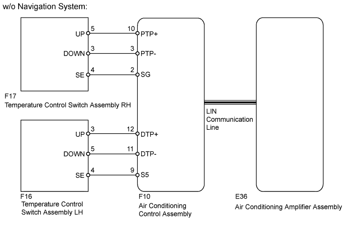
The temperature control switch assembly LH and RH sends the temperature up and down signal to the air conditioning amplifier assembly through the multi-display assembly*1 or the air conditioning control assembly*2.
-
*1: w/ Navigation System
-
*2: w/o Navigation System
WIRING DIAGRAM
INSPECTION PROCEDURE
PROCEDURE
-
CHECK VEHICLE TYPE
-
Check if the vehicle is equipped with the navigation system.
Result Result Proceed to w/ Navigation System A w/o Navigation System B
B 
CHECK LIN COMMUNICATION SYSTEM Click here
A 
-
-
CHECK CAN COMMUNICATION SYSTEM
-
Check the CAN communication system.
OK CAN communication system has no problem. Result Result Proceed to OK A NG (for LHD) B NG (for RHD) C
B 
GO TO CAN COMMUNICATION SYSTEM Click here
C
GO TO CAN COMMUNICATION SYSTEM Click here
A
-
-
CHECK OPERATION
-
Check that the temperature control switches operate.
Result Result Proceed to Temperature control switch LH does not operate A Temperature control switch RH does not operate B Temperature control switch LH and RH do not operate C
B
INSPECT TEMPERATURE CONTROL SWITCH ASSEMBLY RH Click here
C
CHECK MULTI-DISPLAY ASSEMBLY Click here
A
-
-
INSPECT TEMPERATURE CONTROL SWITCH ASSEMBLY LH
-
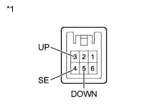
Text in Illustration *1 Component without harness connected
(Temperature Control Switch Assembly LH)
Remove the temperature control switch assembly LH Click here.
-
Measure the resistance according to the value(s) in the table below.
Standard Resistance Tester Connection Switch Condition Specified Condition 3 (UP) - 4 (SE) UP switch pressed Below 1 Ω UP switch not pressed 10 kΩ or higher 5 (DOWN) - 4 (SE) DOWN switch pressed Below 1 Ω DOWN switch not pressed 10 kΩ or higher
NG
REPLACE TEMPERATURE CONTROL SWITCH ASSEMBLY LH Click here
OK
-
-
CHECK HARNESS AND CONNECTOR (TEMPERATURE CONTROL SWITCH ASSEMBLY LH - MULTI-DISPLAY ASSEMBLY)
-
Disconnect the F16 temperature control switch assembly LH connector.
-
Disconnect the F90 multi-display assembly connector.
-
Measure the resistance according to the value(s) in the table below.
Standard Resistance Tester Connection Condition Specified Condition F16-3 (UP) - F90-2 (TEC+) Always Below 1 Ω F16-5 (DOWN) - F90-7 (TEC-) Always Below 1 Ω F16-4 (SE) - F90-6 (AGND) Always Below 1 Ω F16-3 (UP) - Body ground Always 10 kΩ or higher F16-5 (DOWN) - Body ground Always 10 kΩ or higher F16-4 (SE) - Body ground Always 10 kΩ or higher
NG
REPAIR OR REPLACE HARNESS OR CONNECTOR
OK 
REPLACE MULTI-DISPLAY ASSEMBLY Click here
-
-
INSPECT TEMPERATURE CONTROL SWITCH ASSEMBLY RH
-
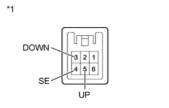
Text in Illustration *1 Component without harness connected
(Temperature Control Switch Assembly RH)
Remove the temperature control switch assembly RH Click here.
-
Measure the resistance according to the value(s) in the table below.
Standard Resistance Tester Connection Switch Condition Specified Condition 5 (UP) - 4 (SE) UP switch pressed Below 1 Ω UP switch not pressed 10 kΩ or higher 3 (DOWN) - 4 (SE) DOWN switch pressed Below 1 Ω DOWN switch not pressed 10 kΩ or higher
NG
REPLACE TEMPERATURE CONTROL SWITCH ASSEMBLY RH Click here
OK
-
-
CHECK HARNESS AND CONNECTOR (TEMPERATURE CONTROL SWITCH ASSEMBLY RH - MULTI-DISPLAY ASSEMBLY)
-
Disconnect the F17 temperature control switch assembly RH connector.
-
Disconnect the F90 multi-display assembly connector.
-
Measure the resistance according to the value(s) in the table below.
Standard Resistance Tester Connection Condition Specified Condition F17-5 (UP) - F90-3 (TES+) Always Below 1 Ω F17-3 (DOWN) - F90-8 (TES-) Always Below 1 Ω F17-4 (SE) - F90-9 (BGND) Always Below 1 Ω F17-5 (UP) - Body ground Always 10 kΩ or higher F17-3 (DOWN) - Body ground Always 10 kΩ or higher F17-4 (SE) - Body ground Always 10 kΩ or higher
NG
REPAIR OR REPLACE HARNESS OR CONNECTOR
OK
REPLACE MULTI-DISPLAY ASSEMBLY Click here
-
-
CHECK MULTI-DISPLAY ASSEMBLY
-
Replace the multi-display assembly with a new or normally functioning one Click here.
-
Check that the temperature control with temperature control switch LH and RH.
OK Temperature control with temperature control switch LH and RH.
NG
PROCEED TO NEXT SUSPECTED AREA SHOWN IN PROBLEM SYMPTOMS TABLE Click here
OK
END (MULTI-DISPLAY ASSEMBLY IS DEFECTIVE)
-
-
CHECK LIN COMMUNICATION SYSTEM
-
Check the LIN communication system.
OK LIN communication system has no problem.
NG
GO TO LIN COMMUNICATION SYSTEM Click here
OK
-
-
CHECK OPERATION
-
Check that the temperature control switches operate.
Result Result Proceed to Temperature control switch LH does not operate A Temperature control switch RH does not operate B Temperature control switch LH and RH do not operate C
B
INSPECT TEMPERATURE CONTROL SWITCH ASSEMBLY RH Click here
C
CHECK AIR CONDITIONING CONTROL ASSEMBLY Click here
A
-
-
INSPECT TEMPERATURE CONTROL SWITCH ASSEMBLY LH
-
Text in Illustration *1 Component without harness connected
(Temperature Control Switch Assembly LH)
Remove the temperature control switch assembly LH Click here.
-
Measure the resistance according to the value(s) in the table below.
Standard Resistance Tester Connection Switch Condition Specified Condition 3 (UP) - 4 (SE) UP switch pressed Below 1 Ω UP switch not pressed 10 kΩ or higher 5 (DOWN) - 4 (SE) DOWN switch pressed Below 1 Ω DOWN switch not pressed 10 kΩ or higher
NG
REPLACE TEMPERATURE CONTROL SWITCH ASSEMBLY LH Click here
OK
-
-
CHECK HARNESS AND CONNECTOR (TEMPERATURE CONTROL SWITCH ASSEMBLY LH - AIR CONDITIONING CONTROL ASSEMBLY)
-
Disconnect the F16 temperature control switch assembly LH connector.
-
Disconnect the F10 air conditioning control assembly connector.
-
Measure the resistance according to the value(s) in the table below.
Standard Resistance Tester Connection Condition Specified Condition F16-3 (UP) - F10-12 (DTP+) Always Below 1 Ω F16-5 (DOWN) - F10-11 (DTP-) Always Below 1 Ω F16-4 (SE) - F10-9 (S5) Always Below 1 Ω F16-3 (UP) - Body ground Always 10 kΩ or higher F16-5 (DOWN) - Body ground Always 10 kΩ or higher F16-4 (SE) - Body ground Always 10 kΩ or higher
NG
REPAIR OR REPLACE HARNESS OR CONNECTOR
OK
REPLACE AIR CONDITIONING CONTROL ASSEMBLY Click here
-
-
INSPECT TEMPERATURE CONTROL SWITCH ASSEMBLY RH
-

Text in Illustration *1 Component without harness connected
(Temperature Control Switch Assembly RH)
Remove the temperature control switch assembly RH Click here.
-
Measure the resistance according to the value(s) in the table below.
Standard Resistance Tester Connection Switch Condition Specified Condition 5 (UP) - 4 (SE) UP switch pressed Below 1 Ω UP switch not pressed 10 kΩ or higher 3 (DOWN) - 4 (SE) DOWN switch pressed Below 1 Ω DOWN switch not pressed 10 kΩ or higher
NG
REPLACE TEMPERATURE CONTROL SWITCH ASSEMBLY RH Click here
OK
-
-
CHECK HARNESS AND CONNECTOR (TEMPERATURE CONTROL SWITCH ASSEMBLY RH - AIR CONDITIONING CONTROL ASSEMBLY)
-
Disconnect the F17 temperature control switch assembly RH connector.
-
Disconnect the F10 air conditioning control assembly connector.
-
Measure the resistance according to the value(s) in the table below.
Standard Resistance Tester Connection Condition Specified Condition F17-5 (UP) - F10-10 (PTP+) Always Below 1 Ω F17-3 (DOWN) - F10-3 (PTP-) Always Below 1 Ω F17-4 (SE) - F10-2 (SG) Always Below 1 Ω F17-5 (UP) - Body ground Always 10 kΩ or higher F17-3 (DOWN) - Body ground Always 10 kΩ or higher F17-4 (SE) - Body ground Always 10 kΩ or higher
NG
REPAIR OR REPLACE HARNESS OR CONNECTOR
OK
REPLACE AIR CONDITIONING CONTROL ASSEMBLY Click here
-
-
CHECK AIR CONDITIONING CONTROL ASSEMBLY
-
Replace the air conditioning control assembly with a new or normally functioning one Click here.
-
Check that the temperature control with temperature control switch LH and RH.
OK Temperature control with temperature control switch LH and RH.
NG
REPLACE AIR CONDITIONING AMPLIFIER ASSEMBLY Click here
OK
END (AIR CONDITIONING CONTROL ASSEMBLY IS DEFECTIVE)
-