AIR CONDITIONING SYSTEM (for Automatic Air Conditioning System) Blower Motor Circuit
DESCRIPTION
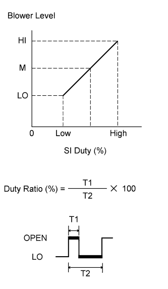
The blower motor is operated by signals from the air conditioning amplifier assembly. The blower motor speed signals are transmitted by changes in the duty ratio.
Duty Ratio:
The duty ratio is the ratio of the blower motor OPEN time (T1) to the total of the blower motor OPEN and LO time (T2).
The blower motor controller controls the blower motor speed.
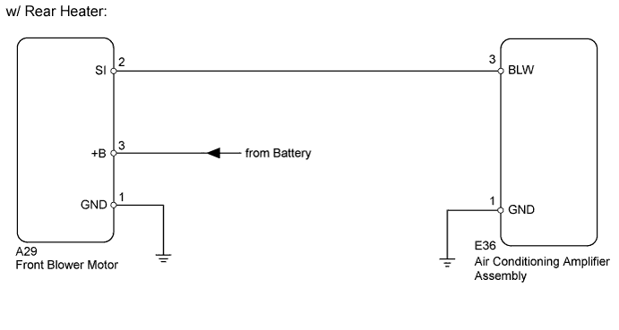
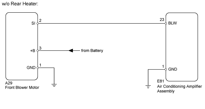
WIRING DIAGRAM
INSPECTION PROCEDURE
PROCEDURE
-
PERFORM ACTIVE TEST USING INTELLIGENT TESTER (FRONT BLOWER MOTOR)
-
Select the Active Test, use the intelligent tester to generate a control command, and then check that the front blower motor operates.
Air Conditioner Tester Display Test Part Control Range Diagnostic Note Blower Motor Front blower motor Min.: 0, Max.: 31 - Result Result Proceed to Front blower motor operates normally A Front blower motor does not operate B Front blower motor operates but does not change speed C
B 
CHECK HARNESS AND CONNECTOR (FRONT BLOWER MOTOR - BODY GROUND) Click here
C
CHECK HARNESS AND CONNECTOR (AIR CONDITIONING AMPLIFIER - FRONT BLOWER MOTOR) Click here
A 
PROCEED TO NEXT CIRCUIT INSPECTION SHOWN IN PROBLEM SYMPTOMS TABLE Click here
-
-
CHECK HARNESS AND CONNECTOR (FRONT BLOWER MOTOR - BODY GROUND)
-
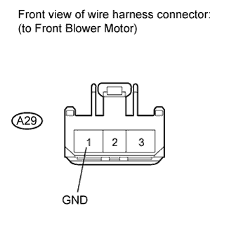
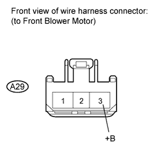
Disconnect the A29 motor connector.
-
Measure the resistance according to the value(s) in the table below.
Standard Resistance Tester Connection Condition Specified Condition A29-1 (GND) - Body ground Always Below 1 Ω
NG 
REPAIR OR REPLACE HARNESS OR CONNECTOR
OK 
-
-
CHECK HARNESS AND CONNECTOR (FRONT BLOWER MOTOR - BATTERY)
-
Disconnect the A29 motor connector.
-
Measure the voltage according to the value(s) in the table below.
Standard Voltage Tester Connection Condition Specified Condition A29-3 (+B) - Body ground Always 11 to 14 V
NG
REPAIR OR REPLACE HARNESS OR CONNECTOR
OK
-
-
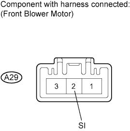
CHECK FRONT BLOWER MOTOR (SI VOLTAGE)
-
Disconnect the E36*1 or E81*2 amplifier connector.
-
Reconnect the A29 motor connector.
-
Measure the voltage according to the value(s) in the table below.
Tech Tips
*1: for LHD
*2: for RHD
Standard Voltage Tester Connection Switch Condition Specified Condition A29-2 (SI) - Body ground Engine switch on (IG) 4.5 to 5.5 V
NG
REPLACE FRONT BLOWER MOTOR Click here
OK
-
-
CHECK HARNESS AND CONNECTOR (AIR CONDITIONING AMPLIFIER - FRONT BLOWER MOTOR)
-
w/ Rear Heater
-
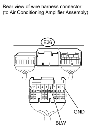
Disconnect the E36 amplifier connector.
-
Measure the voltage according to the value(s) in the table below.
Standard Voltage Tester Connection Switch Condition Specified Condition E36-3 (BLW) - E36-1 (GND) Engine switch on (IG)
Blower switch off
4.5 to 5.5 V
-
-
w/o Rear Heater
-
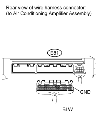
Disconnect the E81 amplifier connector.
-
Measure the voltage according to the value(s) in the table below.
Standard Voltage Tester Connection Switch Condition Specified Condition E81-23 (BLW) - E81-1 (GND) Engine switch on (IG)
Blower switch off
4.5 to 5.5 V
-
NG
REPAIR OR REPLACE HARNESS OR CONNECTOR
OK
REPLACE AIR CONDITIONING AMPLIFIER ASSEMBLY Click here
-
-
CHECK HARNESS AND CONNECTOR (AIR CONDITIONING AMPLIFIER - FRONT BLOWER MOTOR)
-
w/ Rear Heater
-
Disconnect the E36 amplifier connector.
-
Measure the voltage according to the value(s) in the table below.
Standard Voltage Tester Connection Switch Condition Specified Condition E36-3 (BLW) - E36-1 (GND) Engine switch on (IG)
Blower switch off
4.5 to 5.5 V
-
-
w/o Rear Heater
-
Disconnect the E81 amplifier connector.
-
Measure the voltage according to the value(s) in the table below.
Standard Voltage Tester Connection Switch Condition Specified Condition E81-23 (BLW) - E81-1 (GND) Engine switch on (IG)
Blower switch off
4.5 to 5.5 V
-
NG
REPAIR OR REPLACE HARNESS OR CONNECTOR
OK
-
-
CHECK AIR CONDITIONING AMPLIFIER ASSEMBLY (BLW SIGNAL)
-
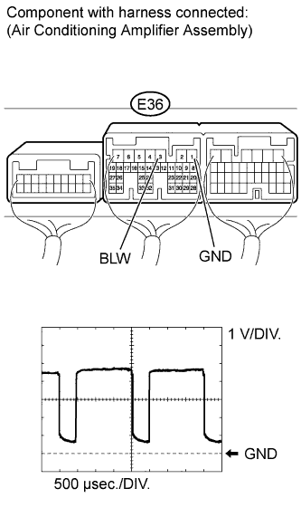
w/ Rear Heater
-
Remove the air conditioning amplifier assembly with its connectors still connected Click here.
-
Using an oscilloscope, check the waveform.
Measurement Condition Item Content Terminal No. (Symbol) E36-3 (BLW) - E36-1 (GND) Tool Setting 1 V/DIV., 500 μsec./DIV. Condition Engine switch on (IG)
Blower switch: off → on
OK Waveform is as shown in the illustration. Tech Tips
Waveform varies with the blower level.
-
-
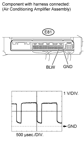
w/o Rear Heater
-
Remove the air conditioning amplifier assembly with its connectors still connected Click here.
-
Using an oscilloscope, check the waveform.
Measurement Condition Item Content Terminal No. (Symbol) E81-23 (BLW) - E81-1 (GND) Tool Setting 1 V/DIV., 500 μsec./DIV. Condition Engine switch on (IG)
Blower switch: OFF → ON
OK Waveform is as shown in the illustration. Tech Tips
Waveform varies with the blower level.
-
NG
REPLACE AIR CONDITIONING AMPLIFIER ASSEMBLY Click here
OK
REPLACE FRONT BLOWER MOTOR Click here
-