AIR CONDITIONING SYSTEM (for Automatic Air Conditioning System) Cooling Box Blower Motor Circuit
DESCRIPTION
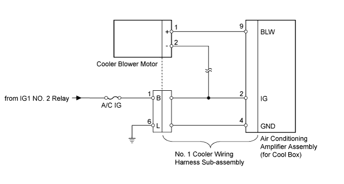
The cooler blower motor is operated by signals from the air conditioning amplifier assembly (for cool box).
WIRING DIAGRAM
INSPECTION PROCEDURE
PROCEDURE
-
INSPECT FUSE (A/C IG)
-
Remove the A/C IG fuse from the cowl side junction block LH.
-
Measure the resistance according to the value(s) in the table below.
Standard Resistance Tester Connection Condition Specified Condition A/C IG fuse Always Below 1 Ω
NG 
REPLACE FUSE
OK 
-
-
CHECK HARNESS AND CONNECTOR (NO. 1 COOLER WIRING HARNESS - BATTERY)
-
Disconnect the No. 1 cooler wiring harness sub-assembly connector.
-
Measure the voltage according to the value(s) in the table below.
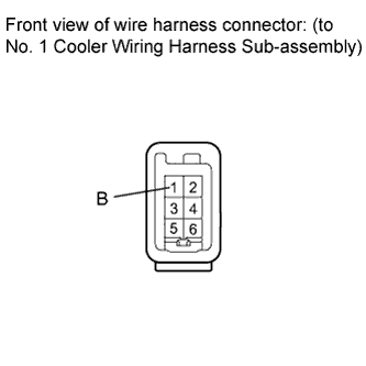
Standard Voltage Tester Connection Switch Condition Specified Condition 1 (B) - Body ground Engine switch off Below 1 V Engine switch on (IG) 11 to 14 V
NG
REPAIR OR REPLACE HARNESS OR CONNECTOR
OK
-
-
CHECK HARNESS AND CONNECTOR (NO. 1 COOLER WIRING HARNESS - BODY GROUND)
-
Disconnect the No. 1 cooler wiring harness sub-assembly connector.
-
Measure the resistance according to the value(s) in the table below.
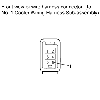
Standard Resistance Tester Connection Condition Specified Condition 6 (L) - Body ground Always Below 1 Ω
NG
REPAIR OR REPLACE HARNESS OR CONNECTOR
OK
-
-
CHECK NO. 1 COOLER WIRING HARNESS SUB-ASSEMBLY (OPERATION)
-
Replace the No. 1 cooler wiring harness sub-assembly with a normal one and check that the condition returns to normal.
OK Same problem does not occur.
NG 
INSPECT COOLER BLOWER MOTOR Click here
OK 
REPLACE NO. 1 COOLER WIRING HARNESS SUB-ASSEMBLY
-
-
INSPECT COOLER BLOWER MOTOR
-
Remove the cooler blower motor Click here.
-
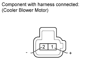
Connect the positive (+) lead from the battery to terminal 1 and negative (-) to terminal 2, then check that the motor operates smoothly.
OK Cooler blower motor operates smoothly.
NG
REPLACE COOLER BLOWER MOTOR Click here
OK
REPLACE AIR CONDITIONING AMPLIFIER ASSEMBLY (for Cool Box) Click here
-