AIRBAG SYSTEM, Diagnostic DTC:B1662/45

| DTC Code | DTC Name |
|---|---|
| B1662/45 | Indicator Light Circuit Malfunction |
DESCRIPTION
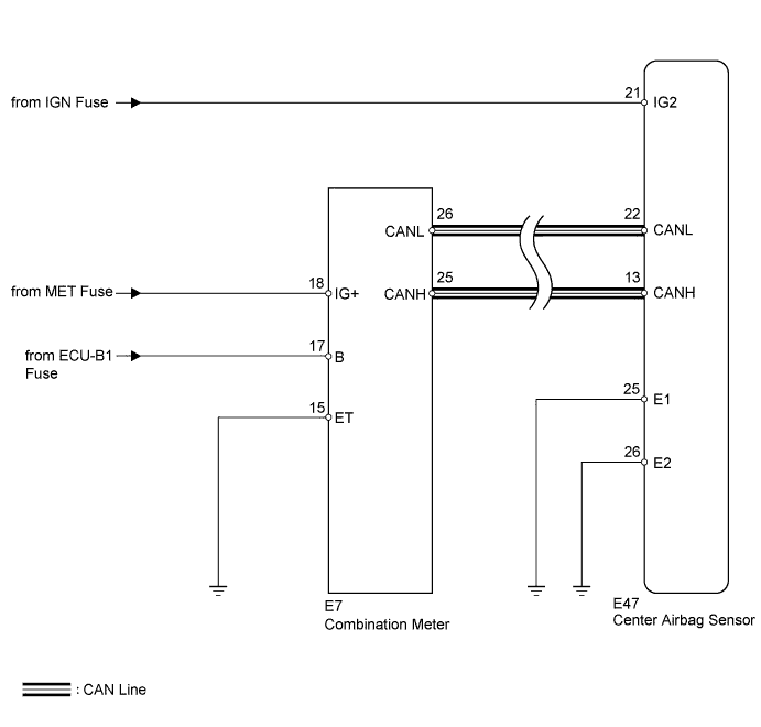
The indicator light circuit consists of the center airbag sensor and the combination meter.
When the center airbag sensor detects a malfunction in the SRS airbag system, the SRS warning light comes on to inform the driver. It also comes on when the source voltage drops, and automatically goes off in approximately 10 seconds after the source voltage returns to normal (DTC is not stored).
The SRS warning light comes on for 6 seconds after the ignition switch is turned to ON and goes off if the system is normal.
When an open circuit is detected, such as when the connector between the combination meter and the center airbag sensor is disconnected, the SRS warning light remains on even when approximately 6 seconds elapsed after the ignition switch is turned to ON.
DTC B1662/45 is stored when a malfunction is detected in the indicator light circuit.
| DTC Code | DTC Detection Condition | Trouble Area |
|---|---|---|
| B1662/45 | When one of the following conditions is met:
|
|
WIRING DIAGRAM
INSPECTION PROCEDURE
Note
-
After turning the ignition switch off, waiting time may be required before disconnecting the cable from the battery terminal. Therefore, make sure to read the disconnecting the cable from the battery terminal notice before proceeding with work Click here.
-
When disconnecting the cable, some systems need to be initialized after the cable is reconnected Click here.
PROCEDURE
-
CHECK CAN COMMUNICATION SYSTEM
-
Check if a CAN communication DTC is output.
Result Result Proceed to DTC is not output A DTC is output (for LHD) B DTC is output (for RHD) C
B 
REPAIR CIRCUITS INDICATED BY OUTPUT DTCS Click here
C
REPAIR CIRCUITS INDICATED BY OUTPUT DTCS Click here
A 
-
-
CHECK BATTERY
-
Measure the voltage of the battery.
Standard Voltage 11 to 14 V
NG
CHECK AND REPLACE BATTERY OR CHARGING SYSTEM
OK
-
-
CHECK CONNECTORS
-
Turn the ignition switch off.
-
Disconnect the cable from the negative (-) battery terminal, and wait for at least 90 seconds.
-
Check that the connectors are properly connected to the center airbag sensor and combination meter.
OK The connectors are properly connected.
NG
CONNECT CONNECTORS PROPERLY
OK
-
-
CHECK HARNESS AND CONNECTOR (SOURCE VOLTAGE OF CENTER AIRBAG SENSOR)
-
Disconnect the connectors from the center airbag sensor.
-
Connect the cable to the negative (-) battery terminal, and wait for at least 2 seconds.
-
Turn the ignition switch to ON.
-
Operate all the components of the electrical system (defogger, wipers, headlights, heater blower, etc.).
-
Measure the voltage according to the value(s) in the table below.
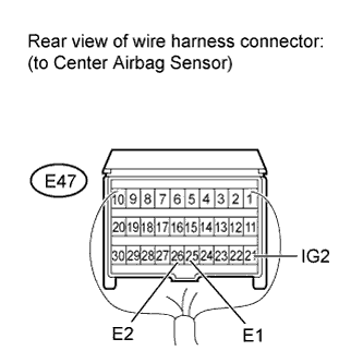
Standard Voltage Tester Connection Switch Condition Specified Condition E47-21 (IG2) - E47-25 (E1) Ignition switch ON 11 to 14 V E47-21 (IG2) - E47-26 (E2) Ignition switch ON 11 to 14 V
NG
REPLACE HARNESS AND CONNECTOR
OK
-
-
CHECK HARNESS AND CONNECTOR (SOURCE VOLTAGE OF COMBINATION METER)
-
Turn the ignition switch off.
-
Disconnect the cable from the negative (-) battery terminal, and wait for at least 90 seconds.
-
Disconnect the E7 connector from the combination meter.
-
Connect the cable to the negative (-) battery terminal, and wait for at least 2 seconds.
-
Measure the voltage according to the value(s) in the table below.
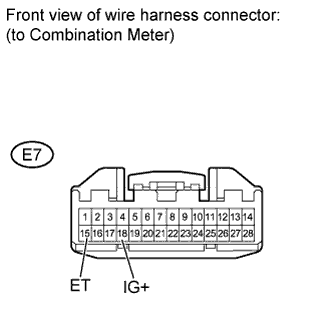
Standard Voltage Tester Connection Switch Condition Specified Condition E7-18 (IG+) - E7-15 (ET) Ignition switch ON 11 to 14 V
NG
REPLACE HARNESS AND CONNECTOR
OK
-
-
CHECK SRS WARNING LIGHT (SHORT TO GROUND)
-
Turn the ignition switch off.
-
Disconnect the cable from the negative (-) battery terminal, and wait for at least 90 seconds.
-
Connect the connector to the combination meter.
-
Connect the cable to the negative (-) battery terminal, and wait for at least 2 seconds.
-
Turn the ignition switch to ON.
-
Check the SRS warning light condition.
OK After the primary check period, SRS warning light goes off for approximately 10 seconds and then remains on. Tech Tips
The primary check period is approximately 6 seconds after the ignition switch is turned ON.
NG
GO TO METER / GAUGE SYSTEM Click here
OK 
REPLACE CENTER AIRBAG SENSOR ASSEMBLY Click here
-