CAMSHAFT POSITION SENSOR INSTALLATION

-
INSTALL VVT SENSOR
-
Apply a light coat of engine oil to the O-ring of the VVT sensor.
Note
-
When reusing the sensor, inspect the O-ring.
-
If the O-ring has scratches or cuts, replace the sensor.
-
-
Install the 4 sensors with the 4 bolts.
- Torque:
- 10 N*m { 102 kgf*cm, 7 ft.*lbf }
-
Connect the 4 sensor connectors.
-
-
INSTALL CAMSHAFT POSITION SENSOR
-
Install the sensor with the bolt.
- Torque:
- 10 N*m { 102 kgf*cm, 7 ft.*lbf }
Note
-
When reusing the sensor, inspect the O-ring.
-
If the O-ring has scratches or cuts, replace the sensor.
-
Connect the sensor connector.
-
-
INSTALL AIR CLEANER HOSE ASSEMBLY
-
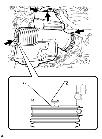
Text in Illustration *1 Groove *2 Protrusion Install the air cleaner hose so that the protrusion of the air cleaner cap aligns with the groove of the hose as shown in the illustration.
-
Tighten the 2 clamps.
- Torque:
- 2.5 N*m { 25 kgf*cm, 22 in.*lbf }
-
Connect the vacuum hose.
-
Connect the No. 2 ventilation hose.
-
-
INSTALL V-BANK COVER SUB-ASSEMBLY
-
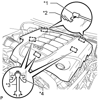
Text in Illustration *1 Bracket *2 Hook *3 Pin *4 Grommet Attach the 2 V-bank cover hooks to the bracket. Then align the 3 V-bank cover grommets with the 3 pins, and press down on the V-bank cover to attach the pins.
-