HEATED OXYGEN SENSOR INSTALLATION

-
INSTALL HEATED OXYGEN SENSOR (for Bank 2 Sensor 2)
-
Temporarily install the sensor to the front exhaust pipe by hand.
-
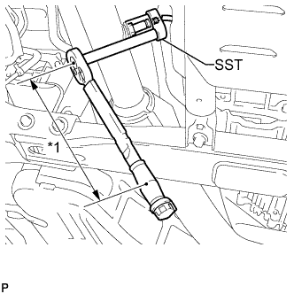
Text in Illustration *1 Fulcrum Length Using SST, tighten the heated oxygen sensor.
- SST
- 09224-00010
- Torque:
- without SST
- 44 N*m { 449 kgf*cm, 32 ft.*lbf }
- with SST
- 40 N*m { 408 kgf*cm, 30 ft.*lbf }
Tech Tips
-
Use a torque wrench with a fulcrum length of 300 mm (11.8 in.). When using a torque wrench with a fulcrum length that is not 300 mm (11.8 in.), calculate the torque specification for the torque wrench and SST based on the "without SST" torque specification Click here.
-
Make sure SST and the wrench are connected in a straight line.
-
Attach the clamp and connect the heated oxygen sensor connector.
-
-
INSTALL HEATED OXYGEN SENSOR (for Bank 1 Sensor 2)
-
Temporarily install the sensor to the front No. 2 exhaust pipe by hand.
-
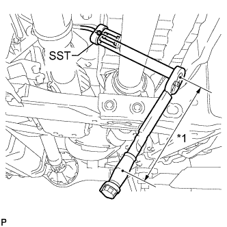
Text in Illustration *1 Fulcrum Length Using SST, tighten the heated oxygen sensor.
- SST
- 09224-00010
- Torque:
- without SST
- 44 N*m { 449 kgf*cm, 32 ft.*lbf }
- with SST
- 40 N*m { 408 kgf*cm, 30 ft.*lbf }
Tech Tips
-
Use a torque wrench with a fulcrum length of 300 mm (11.8 in.). When using a torque wrench with a fulcrum length that is not 300 mm (11.8 in.), calculate the torque specification for the torque wrench and SST based on the "without SST" torque specification Click here.
-
Make sure SST and the wrench are connected in a straight line.
-
Connect the heated oxygen sensor connector.
-
-
INSTALL PROPELLER SHAFT HEAT INSULATOR
-
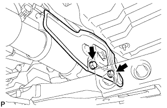
Install the insulator with the 2 bolts.
- Torque:
- 16 N*m { 160 kgf*cm, 12 ft.*lbf }
-
-
INSPECT FOR EXHAUST GAS LEAK
If gas is leaking, tighten the areas necessary to stop the leak. Replace damaged parts as necessary.