- Click here
INSTALL CAMSHAFT TIMING OIL CONTROL VALVE ASSEMBLY (for Exhaust Side of Bank 2)
-
Apply a light coat of engine oil to a new O-ring.
-
Install the O-ring to the camshaft timing oil control valve.
-
Install the camshaft timing oil control valve with the bolt.
10 N*m 102 kgf*cm 7 ft.*lbf -
Connect the camshaft timing oil control valve connector.
-
- Click here
INSTALL CAMSHAFT TIMING OIL CONTROL VALVE ASSEMBLY (for Intake Side of Bank 2)
-
Apply a light coat of engine oil to a new O-ring.
-
Install the O-ring to the camshaft timing oil control valve.
-
Install the camshaft timing oil control valve with the bolt.
10 N*m 102 kgf*cm 7 ft.*lbf -
Connect the camshaft timing oil control valve connector.
-
w/ Secondary Air Injection System:
-
Connect the air pipe with the bolt.
10 N*m 102 kgf*cm 7 ft.*lbf -
Attach the clamp and connect the throttle body connector.
-
-
- Click here
INSTALL CAMSHAFT TIMING OIL CONTROL VALVE ASSEMBLY (for Intake Side of Bank 1)
-
Apply a light coat of engine oil to a new O-ring.
-
Install the O-ring to the camshaft timing oil control valve.
-
Install the camshaft timing oil control valve with the bolt.
10 N*m 102 kgf*cm 7 ft.*lbf -
Connect the camshaft timing oil control valve connector.
-
- Click here
INSTALL CAMSHAFT TIMING OIL CONTROL VALVE ASSEMBLY (for Exhaust Side of Bank 1)
-
Apply a light coat of engine oil to a new O-ring.
-
Install the O-ring to the camshaft timing oil control valve.
-
Install the camshaft timing oil control valve with the bolt.
10 N*m 102 kgf*cm 7 ft.*lbf -
Connect the camshaft timing oil control valve connector.
-
- Click here
INSTALL AIR CLEANER CAP AND HOSE
-
Install the air cleaner cap and hose, and then tighten the hose clamp.
2.5 N*m 25 kgf*cm 22 in.*lbf -
Attach the 4 clamps.
-
Connect the mass air flow meter connector and attach the clamp.
-
Connect the No. 2 PCV hose and No. 1 air hose.
-
- Click here
INSTALL V-BANK COVER SUB-ASSEMBLY
-
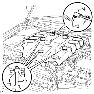
Attach the 2 V-bank cover hooks to the bracket. Then align the 3 V-bank cover grommets with the 3 pins, and press down on the V-bank cover to attach the pins.
Table 1. Text in Illustration *1 Grommet *2 Pin *3 Hook *4 Bracket
-