Click here
Click here
- Click here
INSTALL KNOCK SENSOR
-
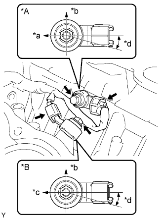
Install the 2 sensors with the 2 bolts as shown in the illustration.
20 N*m 204 kgf*cm 15 ft.*lbf Table 1. Text in Illustration *A for Bank 2 *B for Bank 1 *a Engine Rear *b Top *c Engine Front *d 0 to 15° -
Connect the 2 sensor connectors.
-
- Click here
INSTALL NO. 1 WATER OUTLET PIPE
-
Install the water outlet pipe with the 2 nuts and bolt.
10 N*m 102 kgf*cm 7 ft.*lbf -
Attach the 3 wire harness clamps.
-
- Click here
INSTALL CYLINDER HEAD SUB-ASSEMBLY (for Bank 1)