CAMSHAFT POSITION SENSOR INSTALLATION

-
INSTALL VVT SENSOR (for Exhaust Side of Bank 2)
-
Apply a light coat of engine oil to the O-ring of the VVT sensor.
Note
-
When reusing the VVT sensor, inspect the O-ring.
-
If the O-ring has scratches or cuts, replace the VVT sensor.
-
-
Install the VVT sensor with the bolt.
- Torque:
- 10 N*m { 102 kgf*cm, 7 ft.*lbf }
-
Connect the VVT sensor connector.
-
-
INSTALL VVT SENSOR (for Intake Side of Bank 2)
-
Apply a light coat of engine oil to the O-ring of the VVT sensor.
Note
-
When reusing the VVT sensor, inspect the O-ring.
-
If the O-ring has scratches or cuts, replace the VVT sensor.
-
-
Install the VVT sensor with the bolt.
- Torque:
- 10 N*m { 102 kgf*cm, 7 ft.*lbf }
-
Connect the VVT sensor connector.
-
-
INSTALL VVT SENSOR (for Exhaust Side of Bank 1)
-
Apply a light coat of engine oil to the O-ring of the VVT sensor.
Note
-
When reusing the VVT sensor, inspect the O-ring.
-
If the O-ring has scratches or cuts, replace the VVT sensor.
-
-
Install the VVT sensor with the bolt.
- Torque:
- 10 N*m { 102 kgf*cm, 7 ft.*lbf }
-
Connect the VVT sensor connector.
-
-
INSTALL VVT SENSOR (for Intake Side of Bank 1)
-
Apply a light coat of engine oil to the O-ring of the VVT sensor.
Note
-
When reusing the VVT sensor, inspect the O-ring.
-
If the O-ring has scratches or cuts, replace the VVT sensor.
-
-
Install the VVT sensor with the bolt.
- Torque:
- 10 N*m { 102 kgf*cm, 7 ft.*lbf }
-
Connect the VVT sensor connector.
-
-
INSTALL NO. 1 AIR CLEANER HOSE
-
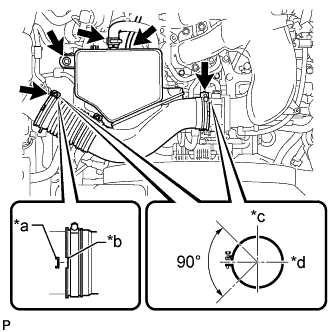
Text in Illustration *a Protrusion *b Groove *c Top *d Front Install the No. 1 air cleaner hose with the 2 hose clamps.
- Torque:
- 2.5 N*m { 25 kgf*cm, 22 in.*lbf }
-
Install the bolt.
- Torque:
- 5.0 N*m { 51 kgf*cm, 44 in.*lbf }
-
Connect the vacuum hose and No. 2 PCV hose.
-
-
INSTALL V-BANK COVER
-
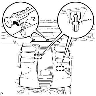
Text in Illustration *1 Pin *2 Hook Attach the 2 V-bank cover hooks to the bracket. Then align the 2 V-bank cover grommets with the 2 pins and press down on the V-bank cover to attach the pins.
-