DESCRIPTION
The fuel injector assemblies are located on the intake manifold. They inject fuel into the cylinders based on the signals from the ECM.
INSPECTION PROCEDURE
Inspect the fuses for circuits related to this system before performing the following inspection procedure.
PROCEDURE
- Click here
CHECK FUEL INJECTOR ASSEMBLY (POWER SOURCE)
-
Disconnect the fuel injector assembly connector.
-
Turn the ignition switch to ON.
-
Measure the voltage according to the value(s) in the table below.
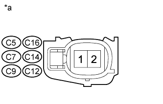
Standard Voltage Cylinder Tester Connection Switch Condition Specified Condition No. 1 C5-1 - Body ground Ignition switch ON 11 to 14 V No. 2 C16-1 - Body ground Ignition switch ON 11 to 14 V No. 3 C7-1 - Body ground Ignition switch ON 11 to 14 V No. 4 C14-1 - Body ground Ignition switch ON 11 to 14 V No. 5 C9-1 - Body ground Ignition switch ON 11 to 14 V No. 6 C12-1 - Body ground Ignition switch ON 11 to 14 V Table 1. Text in Illustration *a Front view of wire harness connector
(to Fuel Injector Assembly)
-
Turn the ignition switch off.
- OKClick here
- NGClick here
-
- Click here
INSPECT FUEL INJECTOR ASSEMBLY
-
Inspect the fuel injector assembly (Click here).
- OKClick here
- NGClick here
-
- Click here
CHECK HARNESS AND CONNECTOR (FUEL INJECTOR ASSEMBLY - ECM)
-
Disconnect the fuel injector assembly connector.
-
Disconnect the ECM connector.
-
Measure the resistance according to the value(s) in the table below.
Standard Resistance Table 2. for LHD Cylinder Tester Connection Condition Specified Condition No. 1 C5-2 - Body ground Always 10 kΩ or higher C5-2 - C45-86 (#10) Always Below 1 Ω No. 2 C16-2 - Body ground Always 10 kΩ or higher C16-2 - C45-109 (#20) Always Below 1 Ω No. 3 C7-2 - Body ground Always 10 kΩ or higher C7-2 - C45-85 (#30) Always Below 1 Ω No. 4 C14-2 - Body ground Always 10 kΩ or higher C14-2 - C45-108 (#40) Always Below 1 Ω No. 5 C9-2 - Body ground Always 10 kΩ or higher C9-2 - C45-84 (#50) Always Below 1 Ω No. 6 C12-2 - Body ground Always 10 kΩ or higher C12-2 - C45-107 (#60) Always Below 1 Ω Table 3. for RHD Cylinder Tester Connection Condition Specified Condition No. 1 C5-2 - Body ground Always 10 kΩ or higher C5-2 - C46-86 (#10) Always Below 1 Ω No. 2 C16-2 - Body ground Always 10 kΩ or higher C16-2 - C46-109 (#20) Always Below 1 Ω No. 3 C7-2 - Body ground Always 10 kΩ or higher C7-2 - C46-85 (#30) Always Below 1 Ω No. 4 C14-2 - Body ground Always 10 kΩ or higher C14-2 - C46-108 (#40) Always Below 1 Ω No. 5 C9-2 - Body ground Always 10 kΩ or higher C9-2 - C46-84 (#50) Always Below 1 Ω No. 6 C12-2 - Body ground Always 10 kΩ or higher C12-2 - C46-107 (#60) Always Below 1 Ω
- OKClick here
- NGClick here
-
- Click here
REPAIR OR REPLACE HARNESS OR CONNECTOR (INTEGRATION RELAY (IG2) - FUEL INJECTOR ASSEMBLY)
- Click here
REPLACE FUEL INJECTOR ASSEMBLYClick here
- Click here
REPAIR OR REPLACE HARNESS OR CONNECTOR
- Click here
REPLACE ECMClick here