SFI SYSTEM, Diagnostic DTC:P2431, P2432, P2433, P2436, P2437, P2438

| DTC Code | DTC Name |
|---|---|
| P2431 | Secondary Air Injection System Air Flow / Pressure Sensor Circuit Range / Performance Bank1 |
| P2432 | Secondary Air Injection System Air Flow / Pressure Sensor Circuit Low Bank1 |
| P2433 | Secondary Air Injection System Air Flow / Pressure Sensor Circuit High Bank1 |
| P2436 | Secondary Air Injection System Air Flow / Pressure Sensor Circuit Range / Performance Bank 2 |
| P2437 | Secondary Air Injection System Air Flow / Pressure Sensor Circuit Low Bank 2 |
| P2438 | Secondary Air Injection System Air Flow / Pressure Sensor Circuit High Bank 2 |
DESCRIPTION
Refer to DTC P0412 Click here.
Refer to DTC P0416 Click here.
| DTC No. | DTC Detection Condition | Trouble Area |
|---|---|---|
| P2431 P2436 |
Pressure sensor indicates a value below 45.6 kPa (342 mmHg), or higher than 135 kPa (1013 mmHg) (2 trip detection logic). |
|
| P2432 P2437 |
While the engine is running, the voltage output of the pressure sensor is below 0.5 V (1 trip detection logic). |
|
| P2433 P2438 |
While the engine is running, the voltage output of the pressure sensor is higher than 4.5 V (1 trip detection logic). |
|
MONITOR DESCRIPTION
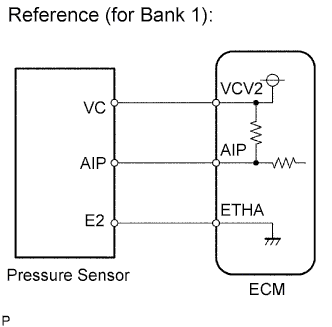
The ECM monitors the pressure in the secondary air passage using the pressure sensor located on the emission control valve set in the secondary air injection system. Using this pressure value, the ECM determines whether the secondary air injection system is malfunctioning or not.
If there is a defect in the sensor or the sensor circuit, the voltage level deviates from the normal operating range. The ECM interprets this deviation as a malfunction in the pressure sensor or circuit and stores a DTC.
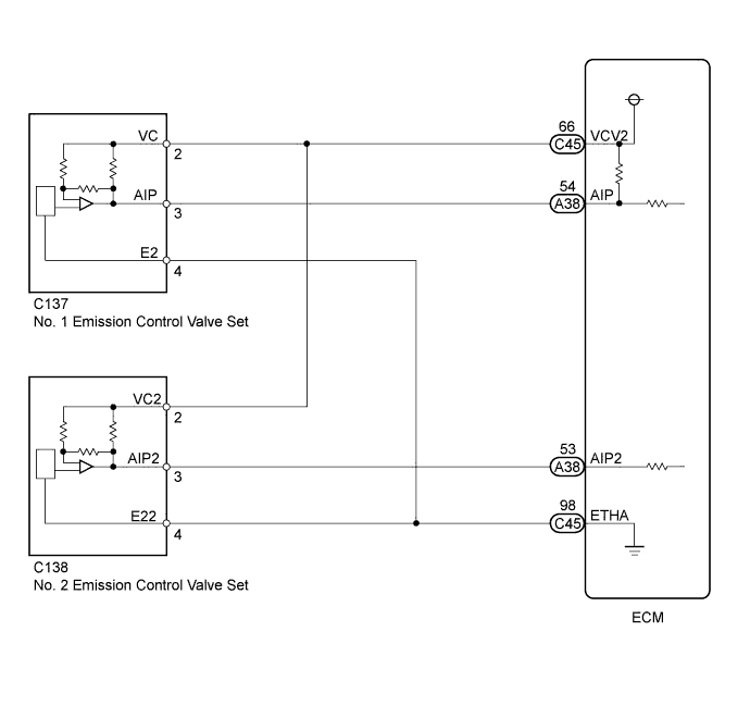
WIRING DIAGRAM
INSPECTION PROCEDURE
Tech Tips
-
Refer to "Data List / Active Test" [Air Pump Pressure (Absolute) and Air Pump2 Pressure (Absolute)] Click here.
-
Read freeze frame data using the GTS. Freeze frame data records the engine condition when malfunctions are detected. When troubleshooting, freeze frame data can help determine if the vehicle was moving or stationary, if the engine was warmed up or not, if the air-fuel ratio was lean or rich, and other data from the time the malfunction occurred.
-
Bank 1 refers to the bank that includes the No. 1 cylinder*.
*: The No. 1 cylinder is the cylinder which is farthest from the transmission.
-
Bank 2 refers to the bank that does not include the No. 1 cylinder.
PROCEDURE
-
CHECK HARNESS AND CONNECTOR (EMISSION CONTROL VALVE SET - ECM)
-
Disconnect the emission control valve set connector.
-
Disconnect the ECM connectors.
-
Measure the resistance according to the value(s) in the table below.
Standard Resistance Tester Connection Condition Specified Condition C137-3 (AIP) - A38-54 (AIP) Always Below 1 Ω C137-2 (VC) - C45-66 (VCV2) Always Below 1 Ω C137-4 (E2) - C45-98 (ETHA) Always Below 1 Ω C138-3 (AIP2) - A38-53 (AIP2) Always Below 1 Ω C138-2 (VC2) - C45-66 (VCV2) Always Below 1 Ω C138-4 (E22) - C45-98 (ETHA) Always Below 1 Ω C137-3 (AIP) or A38-54 (AIP) - Body ground Always 10 kΩ or higher C137-2 (VC) or C45-66 (VCV2) - Body ground Always 10 kΩ or higher C138-3 (AIP2) or A38-53 (AIP2) - Body ground Always 10 kΩ or higher C138-2 (VC2) or C45-66 (VCV2) - Body ground Always 10 kΩ or higher
NG 
REPAIR OR REPLACE HARNESS OR CONNECTOR
OK 
-
-
CHECK TERMINAL VOLTAGE (VC OF EMISSION CONTROL VALVE SET)
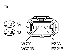
Text in Illustration *A for Bank 1 *B for Bank 2 *a Front view of wire harness connector
(to Emission Control Valve Set)
-
Disconnect the emission control valve set connector.
-
Turn the ignition switch to ON.
-
Measure the voltage according to the value(s) in the table below.
Standard Voltage Tester Connection Switch Condition Specified Condition C137-2 (VC) - C137-4 (E2) Ignition switch ON 4.5 to 5.5 V C138-2 (VC2) - C138-4 (E22) Ignition switch ON 4.5 to 5.5 V
NG
REPLACE ECM Click here
OK
-
-
REPLACE EMISSION CONTROL VALVE SET
-
Replace the emission control valve set.
Tech Tips
-
Replace the No. 1 emission control valve set Click here.
-
Replace the No. 2 emission control valve set Click here.
-
NEXT
-
-
CHECK WHETHER DTC OUTPUT RECURS
-
Start the engine and warm it up.
-
Turn the ignition switch off.
-
Connect the GTS to the DLC3.
-
Turn the ignition switch to ON.
-
Turn the GTS on.
-
Clear the DTCs (if stored) Click here.
-
Enter the following menus: Powertrain / Engine and ECT / Utility / Secondary Air Injection Check / Automatic Mode.
-
Start the engine after the GTS initialization is finished.
-
Perform the System Check operation by pressing ENTER (Next).
-
Perform the following to confirm the secondary air injection system pending codes: Press the Exit button.
-
Check for pending DTCs.
OK No pending DTC is output. -
Turn the ignition switch off.
Note
-
When performing the Secondary Air Injection Check operation after the battery cable has been reconnected, wait for 7 minutes with the ignition switch turned to ON or the engine running.
-
Turn the ignition switch off when the Secondary Air Injection Check operation finishes.
-
NG
REPLACE ECM Click here
OK 
END
-