FUEL TANK REMOVAL

-
DISCHARGE FUEL SYSTEM PRESSURE
-
REMOVE FUEL TANK CAP ASSEMBLY
-
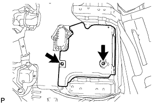
REMOVE NO. 1 FUEL TANK PROTECTOR SUB-ASSEMBLY
-
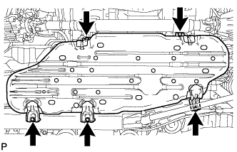
Remove the 5 bolts and No. 1 fuel tank protector sub-assembly.
-
-
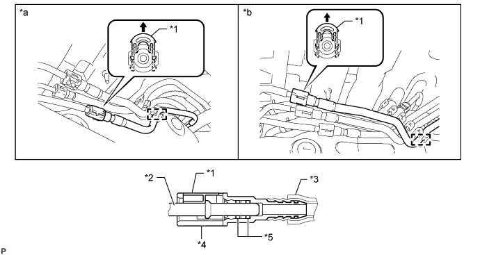
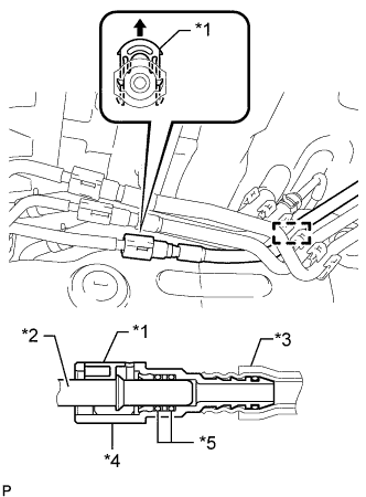
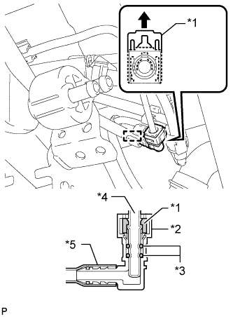
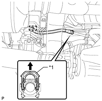
DISCONNECT FUEL TANK MAIN TUBE SUB-ASSEMBLY
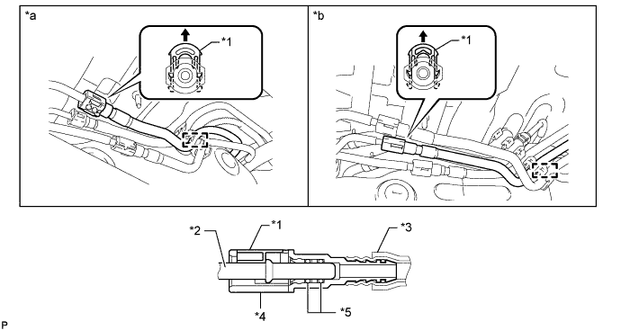
Text in Illustration *1 Retainer *2 Pipe *3 Nylon Tube *4 Connector *5 O-Ring - - *a except G.C.C. Countries *b for G.C.C. Countries 
Pull Up - -
-
Detach the fuel tube clamp.
-
Pull up the retainer and disconnect the fuel tank main tube sub-assembly.
Note
-
Check for foreign matter in the pipe and around the connector. Clean if necessary. Foreign matter may damage the O-ring or cause leaks in the seal between the pipe and connector.
-
Do not use any tools to separate the pipe and connector.
-
Do not forcefully bend or twist the nylon tube.
-
Check for foreign matter on the pipe seal surface. Clean if necessary.
-
Put the pipe and connector ends in plastic bags to prevent damage and foreign matter contamination.
-
If the pipe and connector are stuck together, pinch the connector between your fingers and turn it carefully to disconnect it.
-
-
-
DRAIN FUEL
-
Connect the cable to the negative (-) battery terminal.
Note
When disconnecting the cable, some systems need to be initialized after the cable is reconnected Click here.
-
Connect the intelligent tester to the DLC3.
-
Turn the engine switch on (IG).
Note
Do not start the engine.
-
Turn the intelligent tester on.
-
Enter the following menus: Powertrain / Engine and ECT / Active Test / Control the Fuel Pump / Speed.
CAUTION:
-
Do not smoke or be near an open flame when working on the fuel system.
-
Secure good ventilation.
-
Keep gasoline away from rubber or leather parts.
Tech Tips
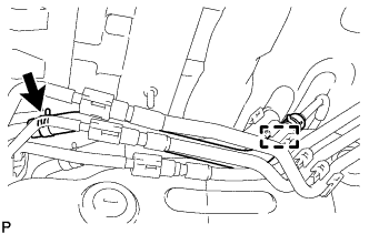
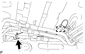
If the fuel pump does not operate, remove the fuel tube joint clip and disconnect the fuel tank return tube, and drain fuel from the port shown in the illustration.
-
-
Disconnect the cable from the negative (-) battery terminal.
Note
When disconnecting the cable, some systems need to be initialized after the cable is reconnected Click here.
-
Disconnect the fuel pump and fuel sender gauge connector.
-
-
PRECAUTION
Note
After turning the engine switch off, waiting time may be required before disconnecting the cable from the battery terminal. Therefore, make sure to read the disconnecting the cable from the battery terminal notice before proceeding with work Click here.
-
DISCONNECT CABLE FROM NEGATIVE BATTERY TERMINAL
Note
When disconnecting the cable, some systems need to be initialized after the cable is reconnected Click here.
-
REMOVE REAR NO. 1 SEAT ASSEMBLY RH (for 60/40 Split Seat Type 40 Side)
-
REMOVE REAR NO. 1 SEAT ASSEMBLY LH (for 60/40 Split Seat Type 60 Side)
-
REMOVE REAR NO. 2 SEAT ASSEMBLY
-
for Face to Face Seat Type:
Remove the rear No. 2 seat assembly Click here.
-
except Face to Face Seat Type:
Remove the rear No. 2 seat assembly Click here.
-
-
REMOVE FRONT FLOOR CARPET ASSEMBLY
-
Turn over the floor carpet.
Tech Tips
Fold back the floor carpet so that the air duct can be removed.
-
-
REMOVE REAR FLOOR NO. 2 SERVICE HOLE COVER
-
Remove the 2 screws and air duct.
-
Remove the rear floor No. 2 service hole cover.
-
-
DISCONNECT NO. 2 FUEL TANK BREATHER HOSE
-
for G.C.C. Countries:
-
Detach the fuel tube clamp.
-
Slide the clip and disconnect the No. 2 fuel tank breather hose from the pipe.
-
-
-
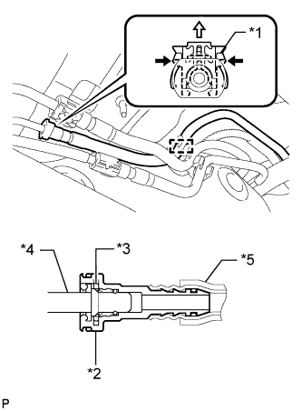
DISCONNECT FUEL TANK RETURN TUBE
Text in Illustration *1 Retainer *2 Pipe *3 Nylon Tube *4 Connector *5 O-Ring - - *a except G.C.C. Countries *b for G.C.C. Countries Pull Up - -
-
Detach the fuel tube clamp.
-
Pull up the retainer and disconnect the fuel tank return tube.
Note
-
Check for foreign matter in the pipe and around the connector. Clean if necessary. Foreign matter may damage the O-ring or cause leaks in the seal between the pipe and connector.
-
Do not use any tools to separate the pipe and connector.
-
Do not forcefully bend or twist the nylon tube.
-
Check for foreign matter on the pipe seal surface. Clean if necessary.
-
Put the pipe and connector ends in plastic bags to prevent damage and foreign matter contamination.
-
If the pipe and connector are stuck together, pinch the connector between your fingers and turn it carefully to disconnect it.
-
-
-
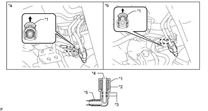
DISCONNECT NO. 1 FUEL EMISSION TUBE SUB-ASSEMBLY
-
Text in Illustration *1 Retainer *2 Pipe *3 Nylon Tube *4 Connector *5 O-Ring Pull Up for G.C.C. Countries:
-
Detach the fuel tube clamp.
-
Pull up the retainer and disconnect the No. 1 fuel emission tube sub-assembly.
Note
-
Check for foreign matter in the pipe and around the connector. Clean if necessary. Foreign matter may damage the O-ring or cause leaks in the seal between the pipe and connector.
-
Do not use any tools to separate the pipe and connector.
-
Do not forcefully bend or twist the nylon tube.
-
Check for foreign matter on the pipe seal surface. Clean if necessary.
-
Put the pipe and connector ends in plastic bags to prevent damage and foreign matter contamination.
-
If the pipe and connector are stuck together, pinch the connector between your fingers and turn it carefully to disconnect it.
-
-
-
Text in Illustration *1 Retainer *2 Connector *3 O-Ring *4 Pipe *5 Nylon Tube Push 
Pull Up except G.C.C. Countries:
-
Detach the fuel tube clamp.
-
Pull the retainer up while pinching it on both sides by hand as shown in the illustration, and disconnect the No. 1 fuel emission tube sub-assembly.
Note
-
Check for foreign matter in the pipe and around the connector. Clean if necessary. Foreign matter may damage the O-ring or cause leaks in the seal between the pipe and connector.
-
Do not use any tools to separate the pipe and connector.
-
Do not forcefully bend or twist the nylon tube.
-
Check for foreign matter on the pipe seal surface. Clean if necessary.
-
Put the pipe and connector ends in plastic bags to prevent damage and foreign matter contamination.
-
If the pipe and connector are stuck together, pinch the connector between your fingers and turn it carefully to disconnect it.
-
-
-
-
DISCONNECT FUEL HOSE
-
for G.C.C. Countries:
-
Detach the fuel tube clamp.
-
Slide the clip and disconnect the fuel hose from the pipe.
-
-
-
DISCONNECT NO. 2 FUEL TANK MAIN TUBE SUB-ASSEMBLY
Text in Illustration *1 Retainer *2 Connector *3 O-Ring *4 Pipe *5 Nylon Tube - - *a except G.C.C. Countries *b for G.C.C. Countries Pull Up - -
-
Detach the fuel tube clamp.
-
Pull up the retainer and disconnect the No. 2 fuel tank main tube sub-assembly.
Note
-
Check for foreign matter in the pipe and around the connector. Clean if necessary. Foreign matter may damage the O-ring or cause leaks in the seal between the pipe and connector.
-
Do not use any tools to separate the pipe and connector.
-
Do not forcefully bend or twist the nylon tube.
-
Check for foreign matter on the pipe seal surface. Clean if necessary.
-
Put the pipe and connector ends in plastic bags to prevent damage and foreign matter contamination.
-
If the pipe and connector are stuck together, pinch the connector between your fingers and turn it carefully to disconnect it.
-
-
-
DISCONNECT NO. 2 FUEL TANK BREATHER TUBE
-
Text in Illustration *1 Retainer *2 Connector *3 O-Ring *4 Pipe *5 Nylon Tube Pull Up except G.C.C. Countries:
-
Detach the fuel tube clamp.
-
Pull up the retainer and disconnect the No. 2 fuel tank breather tube.
Note
-
Check for foreign matter in the pipe and around the connector. Clean if necessary. Foreign matter may damage the O-ring or cause leaks in the seal between the pipe and connector.
-
Do not use any tools to separate the pipe and connector.
-
Do not forcefully bend or twist the nylon tube.
-
Check for foreign matter on the pipe seal surface. Clean if necessary.
-
Put the pipe and connector ends in plastic bags to prevent damage and foreign matter contamination.
-
If the pipe and connector are stuck together, pinch the connector between your fingers and turn it carefully to disconnect it.
-
-
-
-
DISCONNECT FUEL TANK BREATHER TUBE
-
Text in Illustration *1 Retainer Pull Up Detach the fuel tube clamp.
-
Pull up the retainer and disconnect the fuel tank breather tube from the fuel tank to filler pipe sub-assembly.
Note
-
Do not use any tools in this procedure.
-
Check for any dirt and foreign matter contamination in the pipe and around the connector. Clean if necessary. Foreign matter may damage the O-ring or cause leaks in the seal between the pipe and connector.
-
-
-
DISCONNECT FUEL TANK TO FILLER PIPE HOSE
-
Loosen the hose clamp and disconnect the fuel tank to filler pipe hose from the fuel tank to filler pipe sub-assembly.
-
-
REMOVE FUEL TANK SUB-ASSEMBLY
-
Place an engine lifter under the fuel tank sub-assembly.
-
Remove the 2 bolts, 2 clips, 2 pins and 2 fuel tank band sub-assemblies.
-
Slowly lower the engine lifter slightly.
-
-
REMOVE FUEL HOSE
-
for G.C.C. Countries:
Slide the clip and remove the fuel hose from the fuel suction tube sub-assembly.
-
-
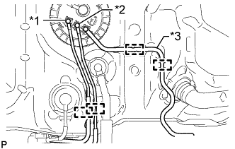
REMOVE FUEL TANK MAIN TUBE, FUEL TANK RETURN TUBE AND NO. 2 FUEL TANK MAIN TUBE SUB-ASSEMBLY
-

Text in Illustration *1 Fuel Tube Joint *2 Tube Joint Clip *3 O-Ring *4 Fuel Suction Plate Sub-assembly Remove the 3 tube joint clips and pull out the 3 fuel tube joints.
Note
-
Remove any dirt and foreign matter on the fuel tube joint before performing this work.
-
Do not allow any scratches or foreign matter on the parts when disconnecting them, as the fuel tube joint contains the O-rings that seal the plug.
-
Perform this work by hand. Do not use any tools.
-
Do not forcibly bend, twist or turn the nylon tube.
-
Protect the disconnected part by covering it with a plastic bag and tape after disconnecting the fuel tubes.
-
-
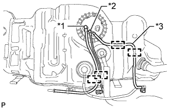
Text in Illustration *1 Fuel Tank Main Tube Sub-assembly *2 Fuel Tank Return Tube Sub-assembly *3 No. 2 Fuel Tank Main Tube Sub-assembly except G.C.C. Countries:
-
Detach the clamp and remove the fuel tank main tube sub-assembly.
-
Detach the clamp and remove the fuel tank return tube sub-assembly.
-
Detach the 2 clamps and remove the No. 2 fuel tank main tube sub-assembly.
-
-
Text in Illustration *1 Fuel Tank Main Tube Sub-assembly *2 Fuel Tank Return Tube Sub-assembly *3 No. 2 Fuel Tank Main Tube Sub-assembly for G.C.C. Countries:
-
Detach the clamp and remove the fuel tank main tube sub-assembly.
-
Detach the clamp and remove the fuel tank return tube sub-assembly.
-
Detach the 2 clamps and remove the No. 2 fuel tank main tube sub-assembly.
-
-
-
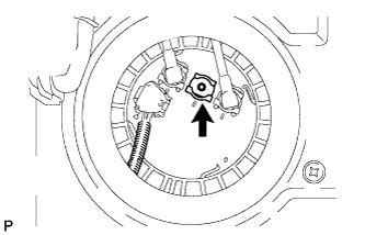
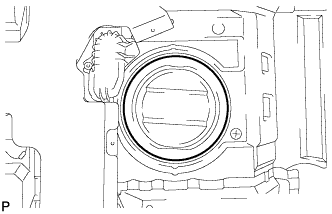
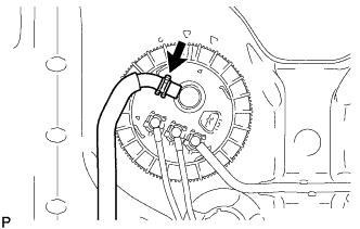
REMOVE FUEL SUCTION WITH PUMP AND GAUGE TUBE ASSEMBLY
-
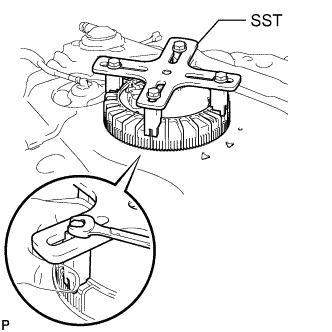
Set SST on the retainer.
- SST
- 09808-14030
Tech Tips
-
Securely attach the claws of SST to the protrusion of the retainer and fix SST in place.
-
Install SST while pressing the claws of SST against the retainer (towards the center of SST).
-
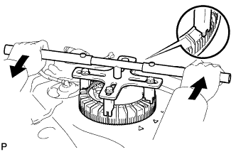
Using SST, loosen the retainer.
- SST
- 09808-14030
Note
-
Do not use any tools other than those specified in this operation. Damage to the retainer or the fuel tank may result.
-
While pressing down on SST so that the claws of SST do not slip off the protrusion of the retainer, turn the retainer counterclockwise to loosen it.
Tech Tips
The protrusion of the retainer fit in the ends of SST.
-
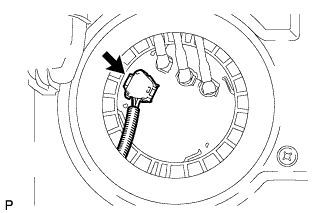
Remove the retainer while holding the fuel suction tube assembly by hand.
-
Remove the gasket from the fuel tank.
-
-
REMOVE FUEL TANK TO FILLER PIPE HOSE
-
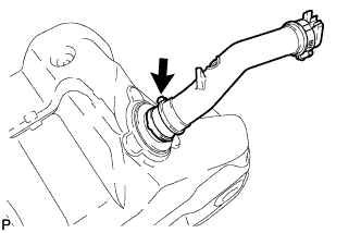
Loosen the hose clamp and remove the fuel tank to filler pipe hose from the fuel tank sub-assembly.
-
-
REMOVE NO. 1 FUEL TANK HEAT INSULATOR
-
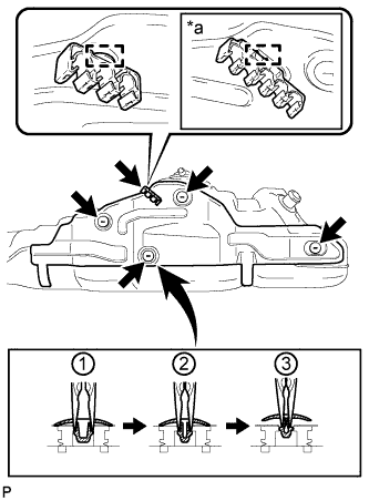
Text in Illustration *a for G.C.C. Countries Remove the fuel tube clamp from the No. 1 fuel tank heat insulator.
-
Using needle-nose pliers, remove the 4 clips shown in the illustration, and then remove the No. 1 fuel tank heat insulator.
-