- Click here
INSTALL NO. 1 FUEL TANK HEAT INSULATOR
-
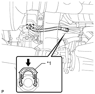
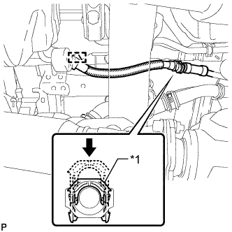
Install the No. 1 fuel tank heat insulator with the 4 clips.
-
Install the fuel tube clamp to the No. 1 fuel tank heat insulator.
-
- Click here
INSTALL FUEL TANK TO FILLER PIPE HOSE
-
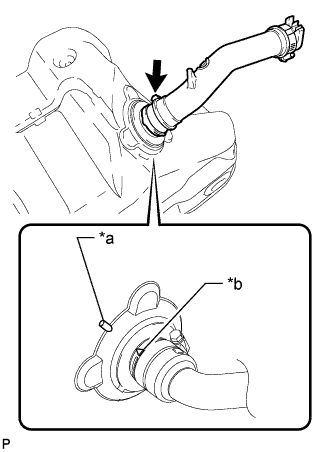
Install the fuel tank to filler pipe hose to the fuel tank sub-assembly as shown in the illustration and tighten the hose clamp.
Table 1. Text in Illustration *a Fuel Tank Side Mark *b Hose Side Mark Tip:
-
Align the fuel tank side mark with the hose side mark when installing the hose.
-
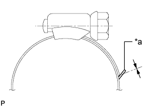
Tighten the hose clamp until the end of the hose clamp contacts the stopper as shown in the illustration.
Table 2. Text in Illustration *a Stopper -
-
- Click here
INSTALL FUEL SUCTION WITH PUMP AND GAUGE TUBE ASSEMBLY
-
Apply a light coat of gasoline or grease to a new gasket, and install it to the fuel tank.
-
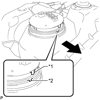
Install the fuel suction with pump and gauge tube assembly into the fuel tank.
Table 3. Text in Illustration *1 Protrusion *2 Groove 
Front Note:Be careful not to bend the arm of the fuel sender gauge.
Tip:Align the protrusion of the fuel suction with pump and gauge tube assembly with the groove of the fuel tank.
-
Put the fuel pump gauge retainer on the fuel tank. While holding the fuel suction with pump and gauge tube assembly, tighten the fuel pump gauge retainer 1 complete turn by hand.
-
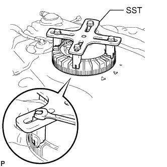
Set SST on the fuel pump gauge retainer.
09808-14030 Tip:
-
Hold the fuel suction with pump and gauge tube assembly upright by hand to make sure that the fuel suction tube gasket is not moved out of position.
-
Engage the claws of SST securely with the fuel pump gauge retainer holes to secure SST.
-
Install SST while pressing the claws of SST against the fuel pump gauge retainer (toward the center of SST).
-
-
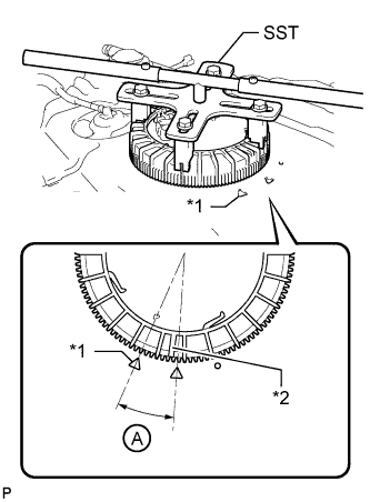
Using SST, tighten the fuel pump gauge retainer until the mark on the fuel pump gauge retainer is within range A on the fuel tank as shown in the illustration.
09808-14030 Table 4. Text in Illustration *1 Fuel Tank Side Mark *2 Fuel Pump Gauge Retainer Side Mark Tip:Fit the tips of SST onto the ribs of the fuel pump gauge retainer.
-
- Click here
INSTALL FUEL TANK MAIN TUBE, FUEL TANK RETURN TUBE AND NO. 2 FUEL TANK MAIN TUBE SUB-ASSEMBLY (for Double Tank Type)
-
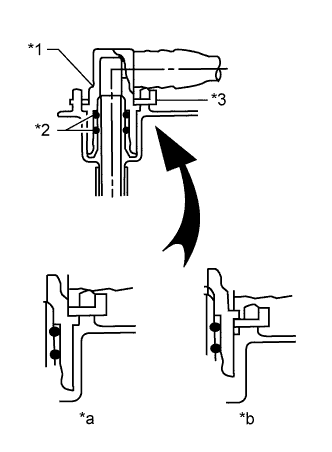
Install the 3 fuel tube joints with the 3 tube joint clips.
Note:
-
Check that there are no scratches or foreign objects on the connecting parts.
-
Check that the fuel tube joints are inserted securely.
-
Check that the tube joint clips are on the collars of the fuel tube joints.
-
After installing the tube joint clips, check that the fuel tube joints cannot be pulled off.
Table 5. Text in Illustration *1 Fuel Tube Joint *2 O-Ring *3 Tube Joint Clip *a CORRECT *b INCORRECT -
-
for G.C.C. Countries:
-
Attach the 2 clamps and install the No. 2 fuel tank main tube sub-assembly.
-
Attach the clamp and install the fuel tank return tube sub-assembly.
-
Attach the clamp and install the fuel tank main tube sub-assembly.
-
-
except G.C.C. Countries:
-
Attach the 2 clamps and install the No. 2 fuel tank main tube sub-assembly.
-
Attach the clamp and install the fuel tank return tube sub-assembly.
-
Attach the clamp and install the fuel tank main tube sub-assembly.
-
-
- Click here
CONNECT FUEL HOSE (for Double Tank Type)
-
for G.C.C. Countries:
Install the fuel hose to the fuel suction tube sub-assembly, and slide the clip to secure the hose.
-
- Click here
INSTALL FUEL TANK MAIN TUBE SUB-ASSEMBLY AND FUEL TANK RETURN TUBE SUB-ASSEMBLY (for Single Tank Type)
-
Install the 2 fuel tube joints with the 2 tube joint clips.
Note:
-
Check that there are no scratches or foreign objects on the connecting parts.
-
Check that the fuel tube joints are inserted securely.
-
Check that the tube joint clips are on the collars of the fuel tube joints.
-
After installing the tube joint clips, check that the fuel tube joints cannot be pulled off.
Table 6. Text in Illustration *1 Fuel Tube Joint *2 O-Ring *3 Tube Joint Clip *a CORRECT *b INCORRECT -
-
Attach the clamp and install the fuel tank return tube sub-assembly.
-
Attach the clamp and install the fuel tank main tube sub-assembly.
-
- Click here
INSTALL FUEL TANK SUB-ASSEMBLY
-
Set the fuel tank sub-assembly on an engine lifter and raise the fuel tank sub-assembly.
Note:Do not allow the fuel tank sub-assembly to contact the vehicle, especially the differential.
-
Raise the engine lifter.
-
Install the 2 fuel tank band sub-assemblies with the 2 pins and 2 clips.
-
Connect the 2 fuel tank band sub-assemblies with the 2 bolts.
40 N*m 408 kgf*cm 30 ft.*lbf
-
- Click here
CONNECT FUEL TANK TO FILLER PIPE HOSE (for Double Tank Type)
-
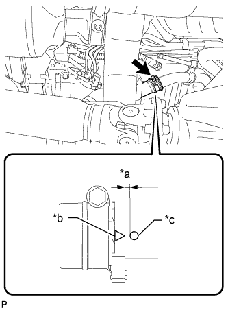
Connect the fuel tank to filler pipe hose to the fuel tank to filler pipe sub-assembly as shown in the illustration and tighten the hose clamp.
Table 7. Text in Illustration *a 0 to 0.3 mm (0 to 0.0118 in.) *b Fuel Tank to Filler Pipe Hose Side Mark *c Fuel Tank Inlet Pipe Side Mark Tip:
-
Install the hose so that the distance between the fuel tank inlet pipe side mark and fuel tank to filler pipe hose side mark is 0 to 0.3 mm (0 to 0.0118 in.) as shown in the illustration.
-
Tighten the hose clamp until the end of the hose clamp contacts the stopper as shown in the illustration.
Table 8. Text in Illustration *a Stopper -
-
- Click here
CONNECT FUEL TANK TO FILLER PIPE HOSE (for Single Tank Type)
-
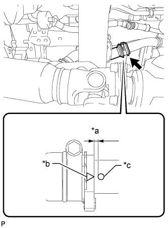
Connect the fuel tank to filler pipe hose to the fuel tank to filler pipe sub-assembly as shown in the illustration and tighten the hose clamp.
Table 9. Text in Illustration *a 0 to 0.3 mm (0 to 0.0118 in.) *b Fuel Tank to Filler Pipe Hose Side Mark *c Fuel Tank Inlet Pipe Side Mark Tip:
-
Install the hose so that the distance between the fuel tank inlet pipe side mark and fuel tank to filler pipe hose side mark is 0 to 0.3 mm (0 to 0.0118 in.) as shown in the illustration.
-
Tighten the hose clamp until the end of the hose clamp contacts the stopper as shown in the illustration.
Table 10. Text in Illustration *a Stopper -
-
- Click here
CONNECT FUEL TANK BREATHER TUBE (for Double Tank Type)
-
Connect the fuel tank breather tube to the fuel tank to filler pipe sub-assembly and push the retainer.
Table 11. Text in Illustration *1 Retainer Push Note:
-
Before installing the tube connectors to the pipes, check if there is any damage or foreign matter in the connectors.
-
After the connection, check if the connectors and pipes are securely connected by trying to pull them apart.
Tip:Push the parts together firmly until a "click" sound is heard.
-
-
Attach the fuel tube clamp.
-
- Click here
CONNECT FUEL TANK BREATHER TUBE (for Single Tank Type)
-
Connect the fuel tank breather tube to the fuel tank to filler pipe sub-assembly and push the retainer.
Table 12. Text in Illustration *1 Retainer Push Note:
-
Before installing the tube connectors to the pipes, check if there is any damage or foreign matter in the connectors.
-
After the connection, check if the connectors and pipes are securely connected by trying to pull them apart.
Tip:Push the parts together firmly until a "click" sound is heard.
-
-
Attach the fuel tube clamp.
-
- Click here
CONNECT NO. 2 FUEL TANK BREATHER TUBE (for Double Tank Type)
-
except G.C.C. Countries:
-
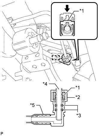
Connect the No. 2 fuel tank breather tube and push the retainer.
Note:
-
Before installing the tube connectors to the pipes, check if there is any damage or foreign matter in the connectors.
-
After the connection, check if the connectors and pipes are securely connected by trying to pull them apart.
Table 13. Text in Illustration *1 Retainer *2 Connector *3 O-Ring *4 Pipe *5 Nylon Tube Push Tip:Push the parts together firmly until a "click" sound is heard.
-
-
Attach the fuel tube clamp.
-
-
-
Click here
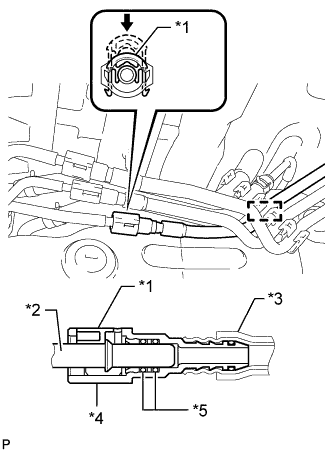
CONNECT NO. 2 FUEL TANK MAIN TUBE SUB-ASSEMBLY (for Double Tank Type)
Table 14. Text in Illustration *1 Retainer *2 Connector *3 O-Ring *4 Pipe *5 Nylon Tube - - *a except G.C.C. Countries *b for G.C.C. Countries Push - -
-
Connect the No. 2 fuel tank main tube sub-assembly and push the retainer.
Note:
-
Before installing the tube connectors to the pipes, check if there is any damage or foreign matter in the connectors.
-
After the connection, check if the connectors and pipes are securely connected by trying to pull them apart.
Tip:Push the parts together firmly until a "click" sound is heard.
-
-
Attach the fuel tube clamp.
-
- Click here
CONNECT FUEL HOSE (for Double Tank Type)
-
for G.C.C. Countries:
-
Connect the fuel hose to the pipe, and slide the clip to secure the hose.
-
Attach the fuel tube clamp.
-
-
- Click here
CONNECT NO. 1 FUEL EMISSION TUBE SUB-ASSEMBLY (for Double Tank Type)
-
except G.C.C. Countries:
-
Connect the No. 1 fuel emission tube sub-assembly and push the retainer.
Note:
-
Before installing the tube connectors to the pipes, check if there is any damage or foreign matter in the connectors.
-
After the connection, check if the connectors and pipes are securely connected by trying to pull them apart.
Table 15. Text in Illustration *1 Retainer *2 Connector *3 O-Ring *4 Pipe *5 Nylon Tube Push Tip:Push the parts together firmly until a "click" sound is heard.
-
-
Attach the fuel tube clamp.
-
-
for G.C.C. Countries:
-
Connect the No. 1 fuel emission tube sub-assembly and push the retainer.
Note:
-
Before installing the tube connectors to the pipes, check if there is any damage or foreign matter in the connectors.
-
After the connection, check if the connectors and pipes are securely connected by trying to pull them apart.
Table 16. Text in Illustration *1 Retainer *2 Pipe *3 Nylon Tube *4 Connector *5 O-Ring Push Tip:Push the parts together firmly until a "click" sound is heard.
-
-
Attach the fuel tube clamp.
-
-
-
Click here
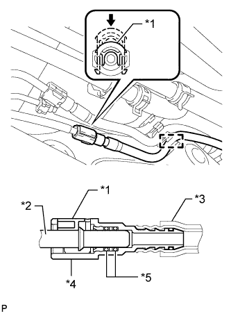
CONNECT FUEL TANK RETURN TUBE (for Double Tank Type)
Table 17. Text in Illustration *1 Retainer *2 Pipe *3 Nylon Tube *4 Connector *5 O-Ring - - *a except G.C.C. Countries *b for G.C.C. Countries Push - -
-
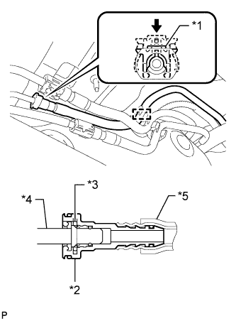
Connect the fuel tank return tube and push the retainer.
Note:
-
Before installing the tube connectors to the pipes, check if there is any damage or foreign matter in the connectors.
-
After the connection, check if the connectors and pipes are securely connected by trying to pull them apart.
Tip:Push the parts together firmly until a "click" sound is heard.
-
-
Attach the fuel tube clamp.
-
- Click here
CONNECT FUEL TANK RETURN TUBE (for Single Tank Type)
-
Connect the fuel tank return tube and push the retainer.
Note:
-
Before installing the tube connectors to the pipes, check if there is any damage or foreign matter in the connectors.
-
After the connection, check if the connectors and pipes are securely connected by trying to pull them apart.
Table 18. Text in Illustration *1 Retainer *2 Pipe *3 Nylon Tube *4 Connector *5 O-Ring Push Tip:Push the parts together firmly until a "click" sound is heard.
-
-
Attach the fuel tube clamp.
-
- Click here
CONNECT NO. 2 FUEL TANK BREATHER HOSE (for Double Tank Type)
-
for G.C.C. Countries:
-
Connect the No. 2 fuel tank breather hose to the pipe, and slide the clip to secure the hose.
-
Attach the fuel pipe clamp.
-
-
- Click here
CONNECT NO. 2 FUEL TANK BREATHER TUBE (for Single Tank Type)
-
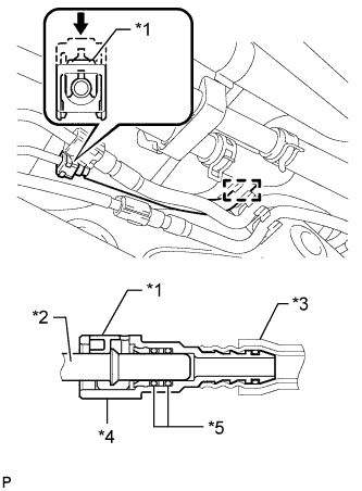
Connect the No. 2 fuel tank breather tube and push the retainer.
Note:
-
Before installing the tube connectors to the pipes, check if there is any damage or foreign matter in the connectors.
-
After the connection, check if the connectors and pipes are securely connected by trying to pull them apart.
Table 19. Text in Illustration *1 Retainer *2 Pipe *3 Nylon Tube *4 Connector *5 O-Ring Push Tip:Push the parts together firmly until a "click" sound is heard.
-
-
Attach the fuel tube clamp.
-
-
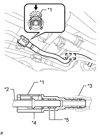
Click here
CONNECT FUEL TANK MAIN TUBE SUB-ASSEMBLY (for Double Tank Type)
Table 20. Text in Illustration *1 Retainer *2 Pipe *3 Nylon Tube *4 Connector *5 O-Ring - - *a except G.C.C. Countries *b for G.C.C. Countries Push - -
-
Connect the fuel tank main tube sub-assembly and push the retainer.
Note:
-
Before installing the tube connectors to the pipes, check if there is any damage or foreign matter in the connectors.
-
After the connection, check if the connectors and pipes are securely connected by trying to pull them apart.
Tip:Push the parts together firmly until a "click" sound is heard.
-
-
Attach the fuel tube clamp.
-
- Click here
CONNECT FUEL TANK MAIN TUBE SUB-ASSEMBLY (for Single Tank Type)
-
Connect the fuel tank main tube sub-assembly and push the retainer.
Note:
-
Before installing the tube connectors to the pipes, check if there is any damage or foreign matter in the connectors.
-
After the connection, check if the connectors and pipes are securely connected by trying to pull them apart.
Table 21. Text in Illustration *1 Retainer *2 Pipe *3 Nylon Tube *4 Connector *5 O-Ring Push Tip:Push the parts together firmly until a "click" sound is heard.
-
-
Attach the fuel tube clamp.
-
- Click here
INSTALL NO. 1 FUEL TANK PROTECTOR SUB-ASSEMBLY
-
Install the No. 1 fuel tank protector sub-assembly with the 5 bolts.
20 N*m 204 kgf*cm 15 ft.*lbf
-
- Click here
INSTALL FUEL TANK CAP ASSEMBLY
- Click here
INSTALL REAR FLOOR NO. 2 SERVICE HOLE COVER
-
Connect the fuel pump and fuel sender gauge connector.
-
Install the rear floor No. 2 service hole cover with new butyl tape.
-
w/ Rear Air Conditioning System:
Install the air duct and 2 screws.
-
- Click here
INSTALL FRONT FLOOR CARPET ASSEMBLY
- Click here
INSTALL FRONT QUARTER TRIM PANEL ASSEMBLY LH
-
w/ Sliding Roof (Click here)
-
w/o Sliding Roof (Click here)
-
- Click here
INSTALL FRONT QUARTER TRIM PANEL ASSEMBLY RH
-
w/ Sliding Roof (Click here)
-
w/o Sliding Roof (Click here)
-
- Click here
INSTALL REAR NO. 2 SEAT ASSEMBLY
-
for Face to Face Seat Type (Click here)
-
except Face to Face Seat Type (Click here)
-
- Click here
INSTALL REAR NO. 1 SEAT ASSEMBLY RH (for 60/40 Split Seat Type 40 Side)
- Click here
INSTALL REAR NO. 1 SEAT ASSEMBLY LH (for 60/40 Split Seat Type 60 Side)
- Click here
CONNECT CABLE TO NEGATIVE BATTERY TERMINAL
Note:When disconnecting the cable, some systems need to be initialized after the cable is reconnected (Click here).
- Click here
ADD FUEL
- Click here
INSPECT FOR FUEL LEAK
-
Make sure that there are no fuel leaks after performing maintenance on the fuel system.
-
Connect the GTS to the DLC3.
-
Turn the engine switch on (IG) and turn the GTS on.
Note:Do not start the engine.
-
Enter the following menus: Powertrain / Engine and ECT / Active Test / Control the Fuel Pump / Speed.
-
Check that there are no leaks from the fuel system.
If there are fuel leaks, repair or replace parts as necessary.
-
Turn the engine switch off.
-
Disconnect the GTS from the DLC3.
-
-