FUEL PUMP DISASSEMBLY

Note
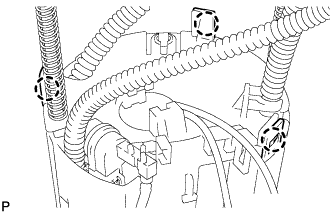
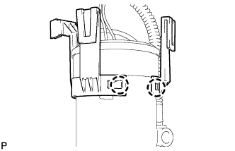
Do not disconnect the hoses indicated in the illustration.
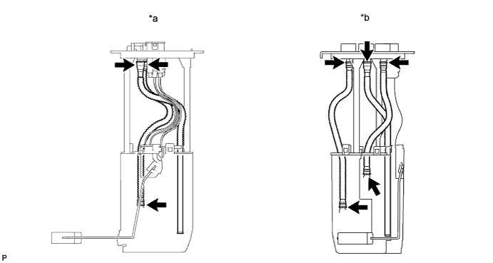
| *a | for Single Tank Type | *b | for Double Tank Type |
-
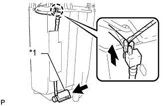
REMOVE FUEL SENDER GAUGE ASSEMBLY
-
Disconnect the fuel sender gauge connector.
-
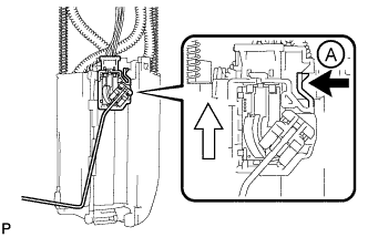
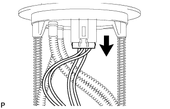
Press down on the sender gauge claw labeled A. Then slide the sender gauge upward to remove it.
Text in Illustration 
Press Down 
Slide
-
-
REMOVE NO. 1 FUEL SUB-TANK (for Single Tank Type)
-
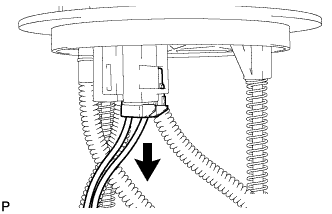
Disconnect the fuel pump connector.
-
Text in Illustration *1 Jet Pump Disconnect the jet pump from the No. 1 fuel sub-tank.
-
Using a small screwdriver, detach the claw from the No. 1 fuel sub-tank.
Tech Tips
Tape the screwdriver tip before use.
-
Detach the tube from the 2 clamps on the No. 1 fuel sub-tank.
-
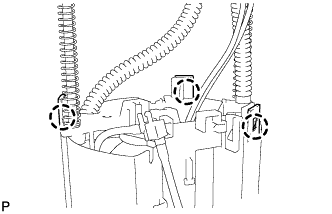
Using a screwdriver, detach the 3 claws from the claw holes.
Note
Do not damage the No. 1 fuel sub-tank.
Tech Tips
Tape the screwdriver tip before use.
-
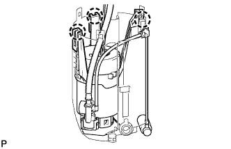
Using a screwdriver, detach the 3 claws from the claw holes and remove the No. 1 fuel sub-tank.
Note
Do not damage the No. 1 fuel sub-tank.
Tech Tips
Tape the screwdriver tip before use.
-
-
REMOVE NO. 1 FUEL SUB-TANK (for Double Tank Type)
-
Disconnect the fuel pump connector.
-
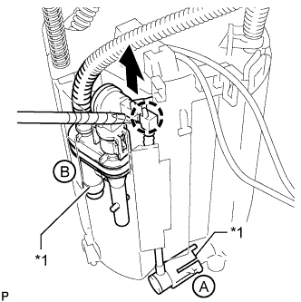
Text in Illustration *1 Jet Pump Disconnect the jet pump (labeled A) from the No. 1 fuel sub-tank.
-
Disconnect the jet pump (labeled B) from the No. 1 fuel sub-tank.
-
Using a small screwdriver, detach the claw from the No. 1 fuel sub-tank.
Tech Tips
Tape the screwdriver tip before use.
-
-
Using a screwdriver, detach the 3 claws from the claw holes.
Note
Do not damage the No. 1 fuel sub-tank.
Tech Tips
Tape the screwdriver tip before use.
-
Using a screwdriver, detach the 3 claws from the claw holes.
Note
Do not damage the No. 1 fuel sub-tank.
Tech Tips
Tape the screwdriver tip before use.
-
-
REMOVE FUEL PUMP
-
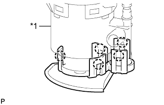
Text in Illustration *1 Fuel Filter Case Using a screwdriver, detach the 5 claws from the claw holes and disconnect the fuel pump from the fuel filter case.
Tech Tips
Tape the screwdriver tip before use.
-
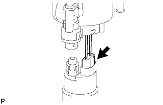
Disconnect the fuel pump wire harness connector from the fuel pump to remove it.
-
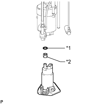
Text in Illustration *1 O-Ring *2 Spacer Remove the O-ring and spacer from the fuel pump.
-
-
REMOVE FUEL MAIN VALVE ASSEMBLY
-

Text in Illustration *1 Fuel Filter Case *2 O-Ring Remove the fuel main valve from the fuel filter case.
-
Remove the 2 O-rings from the fuel main valve.
-
-
REMOVE NO. 1 FUEL SUCTION SUPPORT
-
Detach the 2 claws from the claw holes to remove the fuel suction support.
-