- Click here
DISCHARGE FUEL SYSTEM PRESSURE
CAUTION:
-
Do not disconnect any part of the fuel system until you have discharged the fuel system pressure.
-
After discharging the fuel pressure, place a cloth or equivalent over fittings as you separate them to reduce the risk of fuel spray on yourself or in the engine compartment.
-
Disconnect the fuel pump ECU connector (Click here).
-
Start the engine. After the engine stops, turn the engine switch off.
Tip:DTC P0171/0174 (system too lean) may be stored.
-
Crank the engine again, and then check that the engine does not start.
-
Loosen the fuel tank cap, and then discharge the pressure in the fuel tank completely.
-
Disconnect the cable from the negative (-) battery terminal.
Note:
-
After turning the engine switch off, waiting time may be required before disconnecting the cable from the battery terminal. Therefore, make sure to read the disconnecting the cable from the battery terminal notice before proceeding with work (Click here).
-
When disconnecting the cable, some systems need to be initialized after the cable is reconnected (Click here).
-
-
Connect the fuel pump ECU connector (Click here).
-
- Click here
PRECAUTION
Note:After turning the engine switch off, waiting time may be required before disconnecting the cable from the battery terminal. Therefore, make sure to read the disconnecting the cable from the battery terminal notice before proceeding with work (Click here).
- Click here
DISCONNECT CABLE FROM NEGATIVE BATTERY TERMINAL
Note:When disconnecting the cable, some systems need to be initialized after the cable is reconnected (Click here).
- Click here
REMOVE FRONT FENDER SPLASH SHIELD SUB-ASSEMBLY LH
-
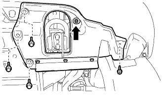
Remove the 3 bolts and screw.
-
Turn the clip indicated by the arrow in the illustration to remove the front fender splash shield sub-assembly LH.
-
- Click here
REMOVE FRONT FENDER SPLASH SHIELD SUB-ASSEMBLY RH
-
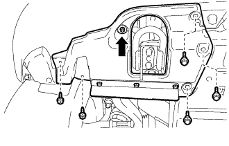
Remove the 3 bolts and 2 screws.
-
Turn the clip indicated by the arrow in the illustration to remove the front fender splash shield sub-assembly RH.
-
- Click here
REMOVE NO. 1 ENGINE UNDER COVER SUB-ASSEMBLY
-
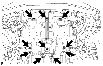
Remove the 10 bolts and No. 1 engine under cover sub-assembly.
-
- Click here
REMOVE V-BANK COVER SUB-ASSEMBLY
-
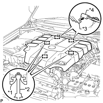
Raise the front of the V-bank cover to detach the 3 pins. Then remove the 2 V-bank cover hooks from the bracket, and remove the V-bank cover.
Table 1. Text in Illustration *1 Grommet *2 Pin *3 Hook *4 Bracket
-
- Click here
REMOVE AIR CLEANER CAP AND HOSE
-
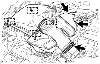
Disconnect the No. 2 PCV hose and No. 1 air hose.
-
Disconnect the mass air flow meter connector and detach the clamp.
-
Detach the 4 clamps.
-
Loosen the hose clamp and remove the air cleaner cap and hose.
-
- Click here
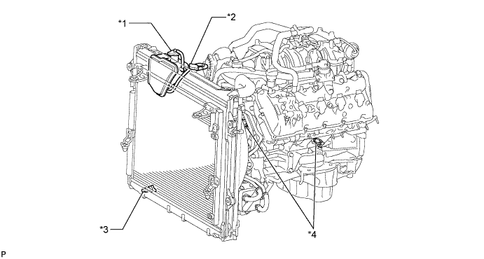
DRAIN ENGINE COOLANT
CAUTION:Do not remove the radiator cap while the engine and radiator are still hot. Pressurized, hot engine coolant and steam may be released and cause serious burns.
-
Loosen the radiator drain cock plug.
-
Remove the radiator cap and drain the coolant.
Tip:Collect the coolant in a container and dispose of it according to the regulations in your area.
-
Loosen the 2 cylinder block drain cock plugs and drain the coolant from the engine.
-
Tighten the 2 cylinder block drain cock plugs.
13 N*m 130 kgf*cm 9 ft.*lbf -
Tighten the radiator drain cock plug by hand.
Table 2. Text in Illustration *1 Reservoir Cap *2 Radiator Cap *3 Radiator Drain Cock Plug *4 Cylinder Block Drain Cock Plug
-
- Click here
REMOVE AIR SWITCHING VALVE ASSEMBLY (w/ Secondary Air Injection System)
-
for Bank 1 (Click here)
-
for Bank 2 (Click here)
-
- Click here
REMOVE NO. 5 WATER BY-PASS PIPE
-
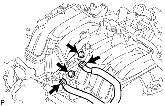
Disconnect the 2 water by-pass hoses and remove the 2 bolts and No. 5 water by-pass pipe.
-
- Click here
REMOVE EGR VALVE BRACKET
-
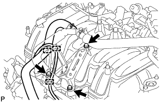
Detach the 2 wire harness clamps and PCV hose clamp.
-
Remove the 3 bolts and EGR valve bracket.
-
- Click here
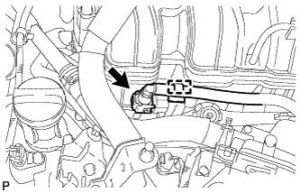
DISCONNECT NO. 2 FUEL TUBE SUB-ASSEMBLY
-
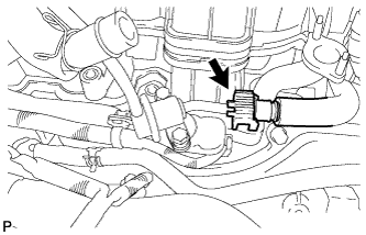
Disconnect the No. 2 fuel tube from the fuel pressure regulator (Click here).
-
- Click here
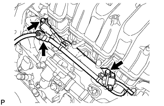
DISCONNECT FUEL TUBE SUB-ASSEMBLY
-
Disconnect the fuel tube from the fuel delivery pipe (Click here).
-
Disconnect the fuel tube from the No. 2 fuel delivery pipe (Click here).
-
- Click here
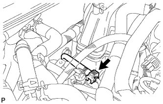
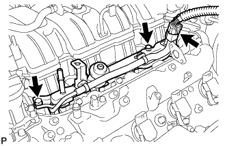
DISCONNECT WIRE HARNESS AND HOSE
-
Disconnect the purge VSV connector.
-
Disconnect the purge line hose from the purge VSV.
-
Disconnect the vacuum switching valve connector (for ACIS).
-
- Click here
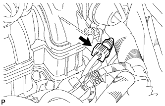
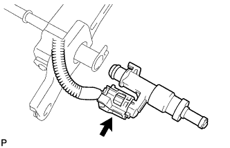
DISCONNECT FUEL HOSE
-
Detach the clamp.
-
Disconnect the fuel hose from the No. 2 fuel delivery pipe (Click here).
-
- Click here
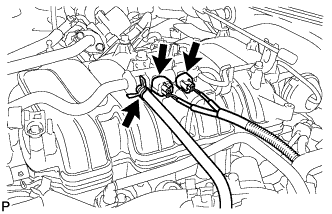
REMOVE FUEL DELIVERY PIPE SUB-ASSEMBLY
-
Disconnect the No. 6 wire harness connector.
-
Remove the 2 bolts and fuel delivery pipe.
Note:When removing the delivery pipe, hold the pipe by both ends and pull it straight upward.
-
Remove the 2 delivery pipe spacers and 4 insulators from the intake manifold.
-
- Click here
REMOVE NO. 2 FUEL DELIVERY PIPE SUB-ASSEMBLY
-
Disconnect the No. 7 wire harness connector.
-
Remove the 2 bolts and No. 2 fuel delivery pipe.
Note:When removing the delivery pipe, hold the pipe by both ends and pull it straight upward.
-
Remove the 2 delivery pipe spacers and 4 insulators from the intake manifold.
-
- Click here
REMOVE FUEL INJECTOR ASSEMBLY
-
Remove the fuel injector from the fuel delivery pipe, and then disconnect the injector connector.
Note: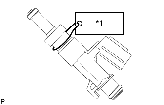
For reinstallation, attach a tag or label to the injector shaft.
Table 3. Text in Illustration *1 No. 1 -
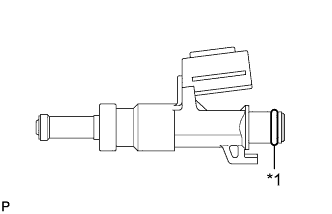
Remove the O-ring from the fuel injector.
Table 4. Text in Illustration *1 O-ring -
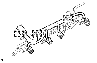
Detach the 3 clamps and then remove the No. 6 wire harness from the fuel delivery pipe.
-
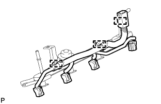
Detach the 3 clamps and then remove the No. 7 wire harness from the No. 2 fuel delivery pipe.
-