FUEL PUMP (for Double Tank Type) INSTALLATION

-
INSTALL FUEL SUCTION WITH PUMP AND GAUGE TUBE ASSEMBLY
-
Apply a light coat of gasoline or grease to a new gasket, and install it to the fuel tank.
-
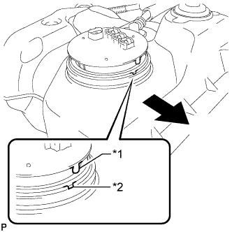
Text in Illustration *1 Protrusion *2 Groove 
Front Install the fuel suction with pump and gauge tube into the fuel tank.
Note
Be careful not to bend the arm of the fuel sender gauge.
Tech Tips
Align the protrusion of the fuel suction with pump and gauge tube with the groove of the fuel tank.
-
Put the retainer on the fuel tank. While holding the fuel suction with pump and gauge tube, tighten the retainer one complete turn by hand.
-
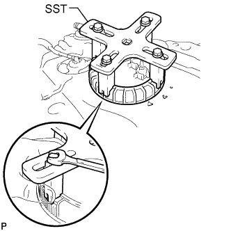
Set SST on the retainer.
- SST
- 09808-14030
Tech Tips
-
Hold the fuel suction tube assembly upright by hand to ensure that the fuel suction tube gasket is not moved out of position.
-
Securely attach the claws of SST to the protrusions of the retainer and fix SST in place.
-
Install SST while pressing the claws of SST against the retainer (toward the center of SST).
-
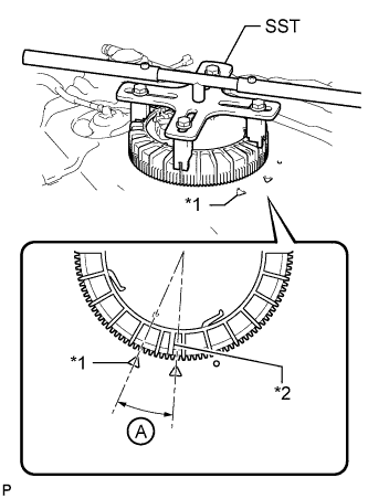
Text in Illustration *1 Fuel Tank Side Mark *2 Retainer Side Mark Using SST, tighten the retainer until the mark on the retainer is within range A on the fuel tank as shown in the illustration.
- SST
- 09808-14030
Tech Tips
Fit the tips of SST onto the ribs of the retainer.
-
-
INSTALL FUEL TANK MAIN TUBE, FUEL TANK RETURN TUBE AND NO. 2 FUEL TANK MAIN TUBE SUB-ASSEMBLY
-
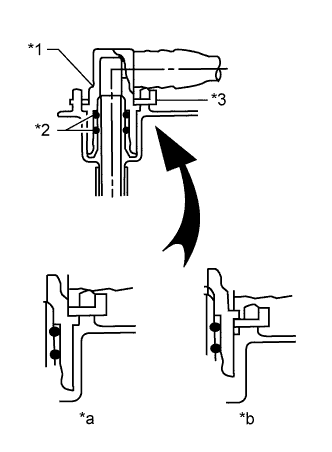
Text in Illustration *1 Fuel Tube Joint *2 O-Ring *3 Tube Joint Clip *a CORRECT *b INCORRECT Install the 3 fuel tank tubes with the 3 tube joint clips.
Note
-
Check that there are no scratches or foreign objects on the connecting parts.
-
Check that the fuel tube joints are inserted securely.
-
Check that the tube joint clips are on the collars of the fuel tube joints.
-
After installing the tube joint clips, check that the fuel tube joints cannot be pulled off.
-
-
for G.C.C. Countries:
-
Attach the 2 clamps and install the No. 2 fuel tank main tube sub-assembly.
-
Attach the clamp and install the fuel tank return tube sub-assembly.
-
Attach the clamp and install the fuel tank main tube sub-assembly.
-
-
except G.C.C. Countries:
-
Attach the 2 clamps and install the No. 2 fuel tank main tube sub-assembly.
-
Attach the clamp and install the fuel tank return tube sub-assembly.
-
Attach the clamp and install the fuel tank main tube sub-assembly.
-
-
-
INSTALL FUEL TANK SUB-ASSEMBLY