CYLINDER BLOCK REASSEMBLY

Note
Before performing these installation procedures, sufficiently clean and remove any foreign matter from the cylinder block, connecting rod and other parts.
-
INSTALL CYLINDER BLOCK STRAIGHT SCREW PLUG
-
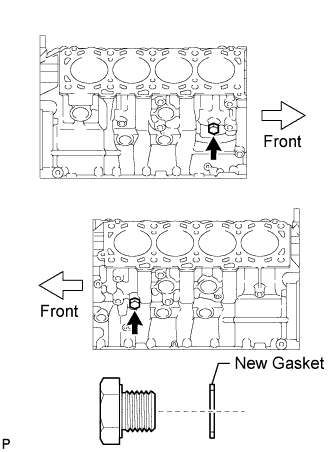
Install 2 new gaskets and the 2 straight screw plugs.
- Torque:
- 38 N*m { 387 kgf*cm, 28 ft.*lbf }
-
-
INSTALL NO. 1 OIL NOZZLE SUB-ASSEMBLY
-
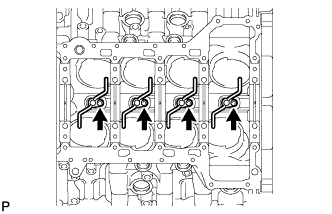
Using a 5 mm hexagon wrench, install the 4 oil nozzles with the 4 bolts.
- Torque:
- 10 N*m { 102 kgf*cm, 7 ft.*lbf }
-
-
INSTALL PISTON PIN HOLE SNAP RING
-
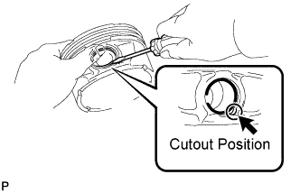
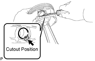
Using a screwdriver, install a new snap ring on one side of the piston pin hole.
Tech Tips
Be sure that the end gap of the snap ring is not aligned with the pin hole cutout portion of the piston.
-
-
INSTALL PISTON WITH PIN SUB-ASSEMBLY
-
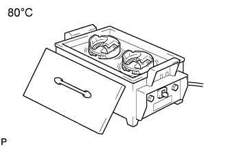
Gradually heat the piston to approximately 80°C (176°F).
-
Coat the piston pin with engine oil.
-
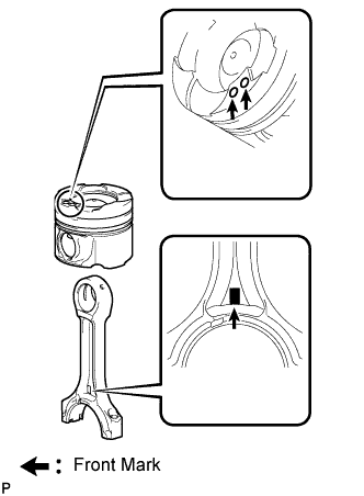
RH:
-
Align the front marks of the piston and connecting rod, and push in the piston pin with your thumb.
Tech Tips
-
The piston and pin are a matched set.
-
The piston has 2 front marks.
-
-
-
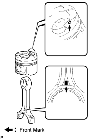
LH:
-
Face the front marks of the piston and connecting rod in opposite directions, and push in the piston pin with your thumb.
Tech Tips
-
The piston and pin are a matched set.
-
The piston has 1 front mark.
-
-
-
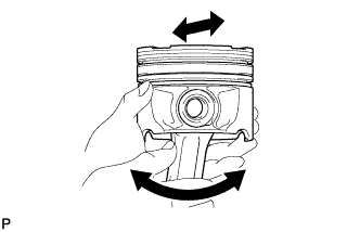
Check the fitting condition between the piston and piston pin by trying to move the piston back and forth on the piston pin.
-
-
INSTALL PISTON PIN HOLE SNAP RING
-
Using a screwdriver, install a new snap ring at the other end of the piston pin hole.
Tech Tips
Be sure that the end gap of the snap ring is not aligned with the pin hole cutout portion of the piston.
-
-
INSTALL PISTON RING SET
-
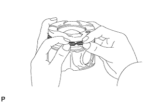
Install the oil ring expander by hand.
-
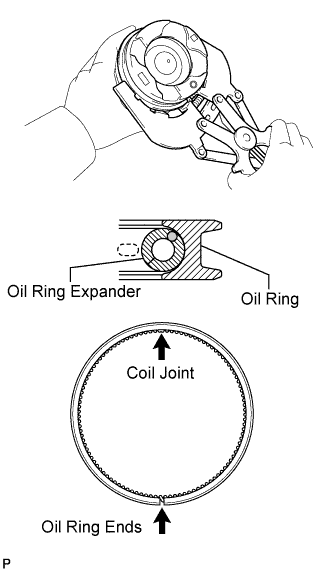
Using a piston ring expander, install the oil ring.
Tech Tips
Align the oil ring ends and coil joint as shown in the illustration.
-
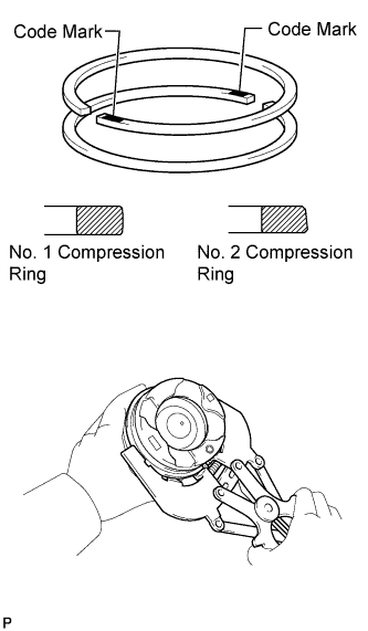
Using a piston ring expander, install the No. 1 and No. 2 compression rings so that the code marks are positioned as shown in the illustration.
Tech Tips
-
w/ EGR System:
Install the No. 1 compression ring with the code mark shown in the table below facing upward.
-
w/o EGR System:
Install the No. 1 compression ring with no code mark. The compression ring can be installed with either side facing upward.
-
Install the No. 2 compression ring with the code mark shown in the table below facing upward.
Standard Code Mark Item Code Mark
(w/ EGR System)
Code Mark
(w/o EGR System)
No. 1 compression ring 1T No mark No. 2 compression ring T2 2T -
-
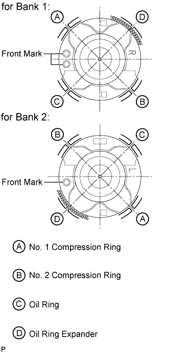
Position the piston rings so that the ring ends are as shown in the illustration.
-
-
INSTALL CONNECTING ROD BEARING
-
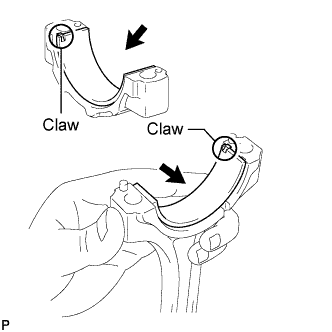
Align the bearing claw with the claw groove of the connecting rod cap.
Note
-
Clean the contact surface of the bearing and connecting rod cap.
-
Do not apply engine oil to the bearing and its contact surface.
-
-
Align the bearing claw with the claw groove of the connecting rod.
Note
-
Clean the contact surface of the bearing and connecting rod.
-
Do not apply engine oil to the bearing and its contact surface.
-
-
-
INSTALL CRANKSHAFT BEARING
Note
Be sure to install the selected bearing.
Tech Tips
Main bearings come in widths of 20.5 mm (0.807 in.) and 22.5 mm (0.886 in.).
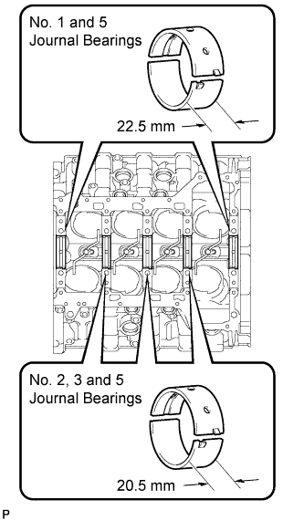
Bearing Width Item Standard Width No. 1 and 5 journal bearings 22.5 mm (0.886 in.) No. 2, 3 and 4 journal bearings 20.5 mm (0.807 in.)
-
Clean each main journal and bearing.
-
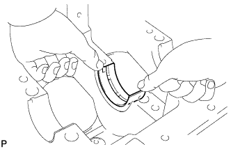
Align the bearing claw with the claw groove of the cylinder block, and push in the 5 upper crankshaft bearings.
Note
-
Clean the contact surface of the bearing and cylinder block.
-
Do not apply engine oil to the bearing and its contact surface.
-
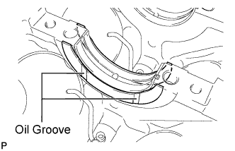
Both sides of the oil groove in the cylinder block should be visible through the oil feed holes in the bearing. The amount visible on each side of the holes should be equal.
-
-
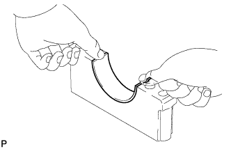
Align the bearing claw with the claw groove of the bearing cap, and push in the 5 lower crankshaft bearings.
Note
-
Clean the contact surface of the bearing and crankshaft bearing cap.
-
Do not apply engine oil to the bearing and its contact surface.
Tech Tips
The number marked on each bearing cap indicates the installation position.
-
-
-
INSTALL CRANKSHAFT
Note
Clean the contact surface of each main journal and crank pin.
-
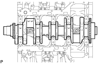
Apply new engine oil to the upper crankshaft bearing and install the crankshaft to the cylinder block.
-
Push the crankshaft toward the rear thrust direction to create clearance, and install a thrust washer to the No. 3 journal position with the oil groove facing the front of the engine.
-
Push the crankshaft toward the forward thrust direction to create clearance, and install a thrust washer to the No. 3 journal position with the oil groove facing the rear of the engine.
-
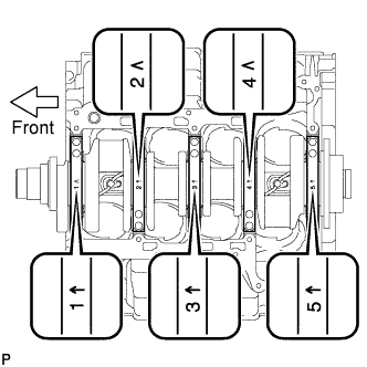
Examine the front marks and numbers and install the bearing caps to the cylinder block.
-
Apply a light coat of engine oil to the threads of the crankshaft bearing cap bolts.
-
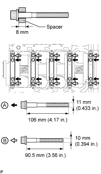
Temporarily install the crankshaft bearing cap bolts labeled A or the bolts labeled B.
Tech Tips
In place of the cylinder block stiffening plates, install 8 mm (0.315 in.) thick spacers to the crankshaft bearing cap bolts.
Standard Length Item Diameter Length A 11 mm (0.433 in.) 106 mm (4.17 in.) B 10 mm (0.394 in.) 90.5 mm (3.56 in.) -
Uniformly tighten the 2 crankshaft bearing cap bolts for each bearing cap in several passes to ensure a proper fit.
Note
Do not tap the bearing cap with a plastic-faced hammer.
-
Remove the crankshaft bearing cap bolts and spacers.
-
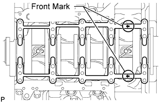
Set the 2 cylinder block stiffening plates on the cylinder block.
Tech Tips
Make sure the arrows on the stiffening plates face the engine front.
-
Step 1:
Tech Tips
-
The crankshaft bearing cap bolts are tightened in 4 progressive steps.
-
If any crankshaft bearing cap bolt is broken or deformed, replace it.
-
Apply a light coat of engine oil to the threads and under the heads of the 20 crankshaft bearing cap bolts A and B.
-
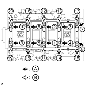
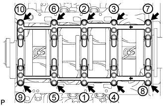
Install the 20 crankshaft bearing cap bolts. Using several steps, tighten the bolts uniformly in the sequence shown in the illustration.
- Torque:
- for bolt A
- 35 N*m { 357 kgf*cm, 26 ft.*lbf }
- for bolt B
- 60 N*m { 612 kgf*cm, 44 ft.*lbf }
-
-
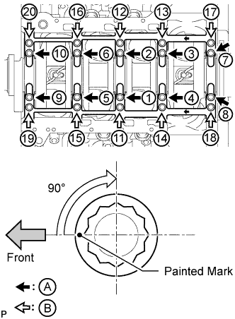
Step 2:
-
Mark the front side of the crankshaft bearing cap bolts A and B with paint.
-
Tighten the crankshaft bearing cap bolts A and B 90° in the sequence shown in the illustration.
-
-
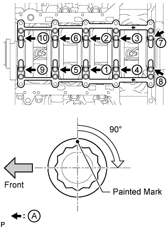
Step 3:
-
Tighten the crankshaft bearing cap bolts A another 90° in the sequence shown in the illustration.
-
-
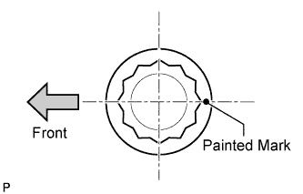
Check that the painted marks of bolt A are now at a 180° angle to the front.
-
Check that the painted marks of bolt B are now at a 90° angle to the front.
-
Check that the crankshaft turns smoothly.
-
Step 4:
-
Using several steps, install the 10 crankshaft bearing cap bolts uniformly in the sequence shown in the illustration.
- Torque:
- 56 N*m { 571 kgf*cm, 41 ft.*lbf }
-
Check that the crankshaft turns smoothly.
-
-
-
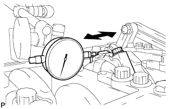
INSPECT CRANKSHAFT THRUST CLEARANCE
-
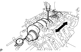
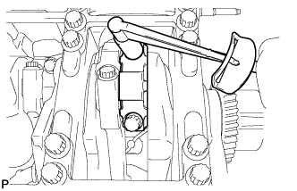
Using a dial indicator, measure the thrust clearance while prying the crankshaft back and forth with a screwdriver.
Standard thrust clearance 0.02 to 0.22 mm (0.000787 to 0.00866 in.) Maximum thrust clearance 0.30 mm (0.0118 in.) If the thrust clearance is more than the maximum, replace the thrust washers as a set.
Standard thrust washer thickness 2.44 to 2.49 mm (0.0961 to 0.0980 in.) If necessary, replace the crankshaft.
-
-
INSTALL PISTON SUB-ASSEMBLY WITH CONNECTING ROD
-
Apply engine oil to the cylinder walls, pistons, and the surfaces of the connecting rod bearings.
-
Check the positions of the piston ring ends.
-
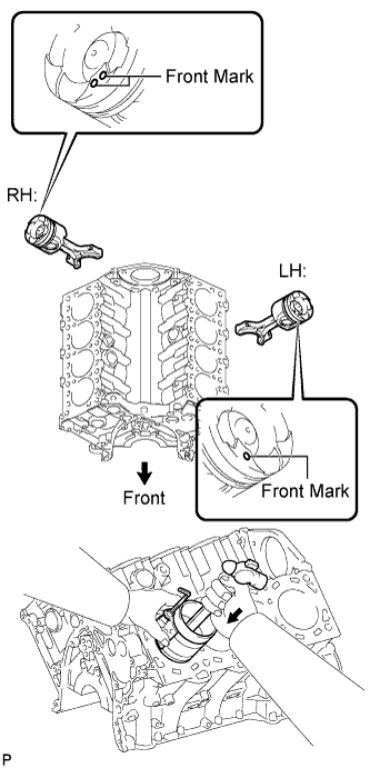
Using a hammer handle and piston ring compressor, press a piston and connecting rod assembly into each cylinder with the front mark of the piston facing forward.
-
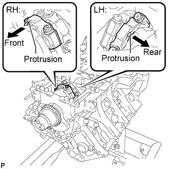
Install the connecting rod cap so that its protrusion is facing the correct direction.
Note
Match the numbered connecting rod cap with the connecting rod.
-
Apply a light coat of engine oil to the threads and under the heads of the connecting rod cap bolts.
-
Step 1:
-
Install and alternately tighten the bolts of the connecting rod cap in several steps.
- Torque:
- 35 N*m { 357 kgf*cm, 26 ft.*lbf }
Tech Tips
-
The connecting rod cap bolts are tightened in 2 progressive steps.
-
If any connecting rod cap bolt is broken or deformed, replace it.
-
-
Step 2:
-
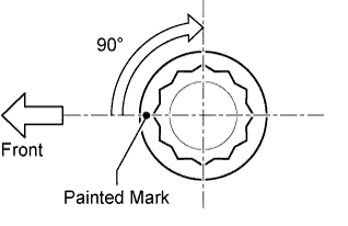
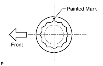
Mark the front side of each connecting rod cap bolt with paint.
-
Tighten the cap bolts 90°.
-
-
Check that the painted marks are now at a 90° angle to the front.
-
Check that the crankshaft turns smoothly.
-
-
INSPECT CONNECTING ROD THRUST CLEARANCE
-
Using a dial indicator, measure the thrust clearance while moving the connecting rod back and forth.
Standard thrust clearance 0.14 to 0.54 mm (0.00551 to 0.0213 in.) Maximum thrust clearance 0.60 mm (0.0236 in.) If the thrust clearance is more than the maximum, replace one or more connecting rods as necessary.
If necessary, replace the crankshaft.
-