CYLINDER HEAD INSPECTION

-
INSPECT CAMSHAFT
-
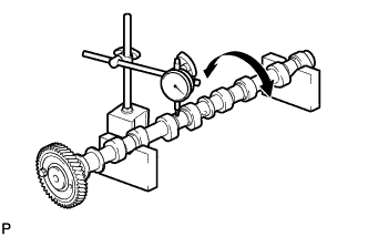
Inspect the camshaft for runout.
-
Place the camshaft on V-blocks.
-
Using a dial indicator, measure the runout at the center journal.
Maximum runout 0.03 mm (0.00118 in.) If the runout is more than the maximum, replace the camshaft.
-
-
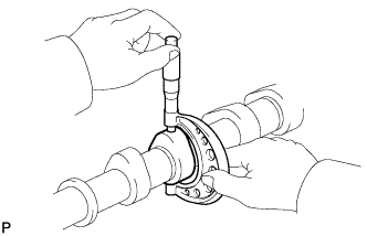
Inspect the cam lobe height.
-
Using a micrometer, measure the cam lobe height.
Standard Cam Lobe Height Item Specified Condition No. 2 and No. 3 camshaft
(intake)
37.277 to 37.387 mm (1.468 to 1.472 in.) No. 1 and No. 4 camshaft
(exhaust)
38.324 to 38.434 mm (1.509 to 1.513 in.) Minimum Cam Lobe Height Item Specified Condition No. 2 and No. 3 camshaft
(intake)
37.277 mm (1.468 in.) No. 1 and No. 4 camshaft
(exhaust)
38.324 mm (1.509 in.) If the cam lobe height is less than the minimum, replace the camshaft.
-
-
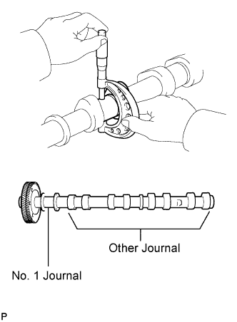
Inspect the camshaft journal diameter.
-
Using a micrometer, measure the journal diameter.
Standard Journal Diameter Item Specified Condition No. 1 journal 29.969 to 29.985 mm (1.180 to 1.181 in.) Other journal 26.969 to 26.985 mm (1.0618 to 1.0624 in.) If the journal diameter is not as specified, check the oil clearance.
-
-
-
INSPECT CAMSHAFT OIL CLEARANCE
-
Clean the camshaft bearing caps and camshaft journals.
-
Place the camshafts on the cylinder head.
-
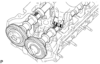
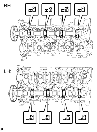
Lay a strip of Plastigage across each of the camshaft journals.
-
Temporarily install the camshaft bearing cap with the 4 bolts by hand.
Note
Do not turn the camshafts.
-
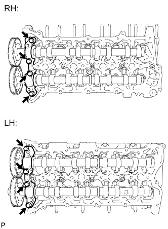
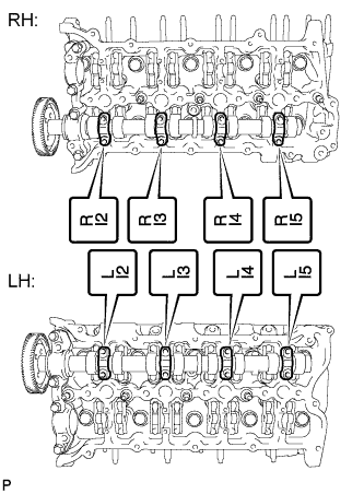
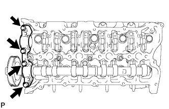
Install the No. 3 camshaft bearing caps with the 16 bolts.
-
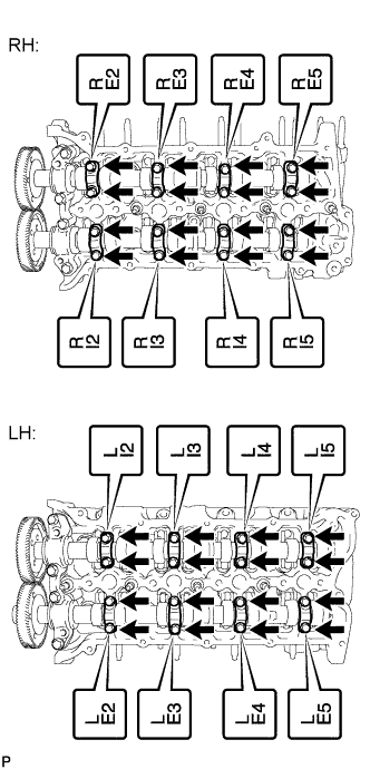
Confirm the marks and numbers on the camshaft bearing caps and place them in their proper position and direction.
-
Temporarily install the 16 bolts.
-
-
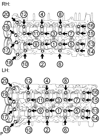
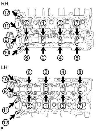
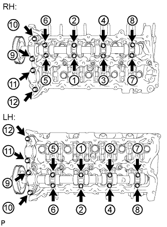
Uniformly tighten the 20 bolts in several steps in the order shown in the illustration.
- Torque:
- for 12 mm head bolt of No. 1 and No. 4 camshaft bearing cap
- 21 N*m { 214 kgf*cm, 15 ft.*lbf }
- for 10 mm head bolt of No. 3 camshaft bearing cap
- 10 N*m { 102 kgf*cm, 7 ft.*lbf }
-
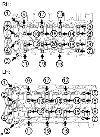
Uniformly loosen and remove the 20 bolts in the sequence shown in the illustration.
-
Measure the Plastigage at its widest point.
Standard oil clearance 0.025 to 0.062 mm (0.000984 to 0.00244 in.) Maximum oil clearance 0.072 mm (0.00283 in.) If the oil clearance is more than the maximum, replace the camshaft.
If necessary, replace the cylinder head sub-assembly.
-
Remove the Plastigage completely.
-
Remove the camshafts.
-
-
INSPECT NO. 2 AND NO. 3 CAMSHAFT THRUST CLEARANCE (for Intake Camshaft)
-
Install the No. 2 and No. 5 camshaft bearing caps to the cylinder head.
-
Place the camshafts on the cylinder head.
-
Temporarily install the No. 1 and No. 4 camshaft bearing caps with the 4 bolts by hand.
Note
Do not turn the camshafts.
-
Install the No. 3 camshaft bearing caps.
-
Confirm the marks and numbers on the camshaft bearing caps and place them in their proper position and direction.
-
Temporarily install the 16 bolts.
-
-
Uniformly tighten the 24 bolts in several steps in the order shown in the illustration.
- Torque:
- for 12 mm head bolt of No. 1 and No. 4 camshaft bearing cap
- 21 N*m { 214 kgf*cm, 15 ft.*lbf }
- for 10 mm head bolt of No. 3 camshaft bearing cap
- 10 N*m { 102 kgf*cm, 7 ft.*lbf }
-
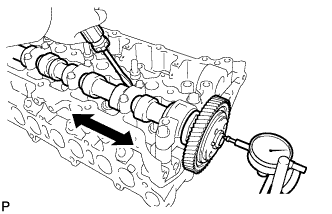
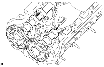
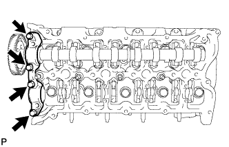
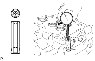
Using a dial indicator, measure the thrust clearance while moving the camshaft back and forth.
Standard thrust clearance 0.035 to 0.160 mm (0.00138 to 0.00630 in.) Maximum thrust clearance 0.180 mm (0.00709 in.) If the thrust clearance is more than the maximum, replace the camshaft.
If necessary, replace the cylinder head sub-assembly.
-
-
INSPECT NO. 1 AND NO. 4 CAMSHAFT THRUST CLEARANCE (for Exhaust Camshaft)
-
Install the No. 2 and No. 5 camshaft bearing caps to the cylinder head.
-
Place the camshafts on the cylinder head.
-
Temporarily install the No. 1 and No. 4 camshaft bearing caps with the 4 bolts by hand.
Note
Do not turn the camshafts.
-
Install the No. 3 camshaft bearing caps.
-
Confirm the marks and numbers on the camshaft bearing caps and place them in their proper position and direction.
-
Temporarily install the 16 bolts.
-
-
Uniformly tighten the 24 bolts in several steps in the order shown in the illustration.
- Torque:
- for 12 mm head bolt of No. 1 and No. 4 camshaft bearing cap
- 21 N*m { 214 kgf*cm, 15 ft.*lbf }
- for 10 mm head bolt of No. 3 camshaft bearing cap
- 10 N*m { 102 kgf*cm, 7 ft.*lbf }
-
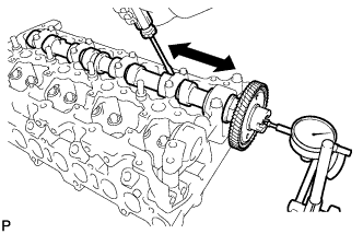
Using a dial indicator, measure the thrust clearance while moving the camshaft back and forth.
Standard thrust clearance 0.035 to 0.160 mm (0.00138 to 0.00630 in.) Maximum thrust clearance 0.180 mm (0.00709 in.) If the thrust clearance is more than the maximum, replace the camshafts.
If necessary, replace the cylinder head sub-assembly.
-
-
INSPECT VALVE ROCKER ARM SUB-ASSEMBLY
-
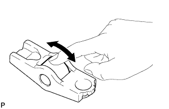
Turn the roller by hand to check that it turns smoothly.
If the roller does not turn smoothly, replace the valve rocker arm.
-
-
INSPECT VALVE LASH ADJUSTER ASSEMBLY
Note
-
Keep the adjuster free from dirt and foreign objects.
-
Use only clean engine oil.
-
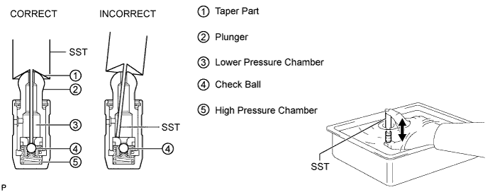
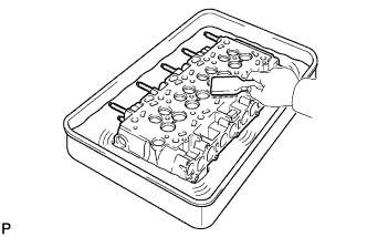
Place the lash adjuster into a container full of new engine oil.
-
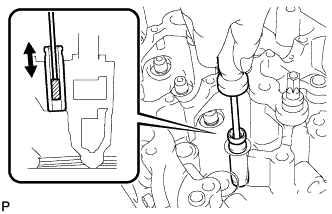
Insert SST tip into the lash adjuster plunger and use the tip to press down on the check ball inside the plunger.
- SST
- 09276-75010
-
Squeeze SST and the lash adjuster together to move the plunger up and down 5 to 6 times.
-
Check the movement of the plunger and bleed air.
OK Plunger moves up and down. Note
When bleeding high-pressure air from the compression chamber, make sure that the tip of SST is actually pressing the check ball as shown in the illustration. If the check ball is not pressed, air will not bleed.
-
After bleeding the air, remove SST. Then try to quickly and firmly press the plunger with your fingers.
OK Plunger can be pressed 3 times. If the plunger can still be compressed after pressing it 3 times, replace the lash adjuster with a new one.
-
-
INSPECT INNER COMPRESSION SPRING
-
Inspect the inner compression spring deviation.
-
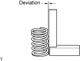
Using a steel square, measure the deviation of the inner compression spring.
Maximum deviation 1.5 mm (0.0591 in.) If the deviation is more than the maximum, replace the inner compression spring.
-
-
Inspect the inner compression spring free length.
-
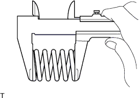
Using a vernier caliper, measure the free length of the inner compression spring.
Standard free length 45.9 mm (1.81 in.) If the free length is not as specified, replace the inner compression spring.
-
-
Inspect the inner compression spring tension.
-
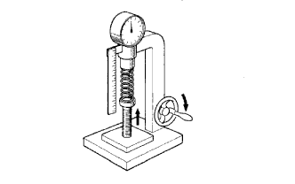
Using a spring tester, measure the tension of the inner compression spring at the specified installed length.
Installed tension 219 to 242 N (22 to 25 kgf, 49.2 to 54.4 lbf) at 31.0 mm (1.22 in.) If the installed tension is not as specified, replace the inner compression spring.
-
-
-
CLEAN VALVE
-
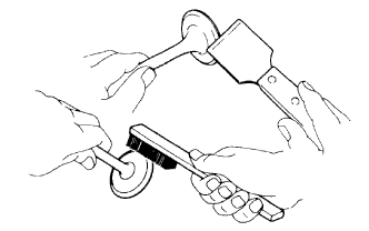
Using a gasket scraper, chip off any carbon from the valve head.
Note
Be careful not to damage the valve face.
-
Using a wire brush, thoroughly clean the valve.
-
-
INSPECT VALVE
-
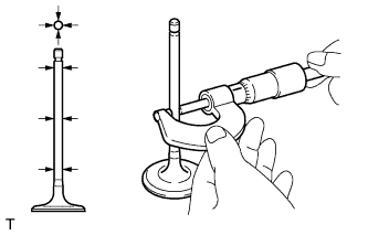
Inspect the valve stem diameter.
-
Using a micrometer, measure the diameter of the valve stem.
Standard Valve Stem Diameter Item Specified Condition Intake 5.970 to 5.985 mm (0.2350 to 0.2356 in.) Exhaust 5.960 to 5.975 mm (0.2346 to 0.2352 in.)
-
-
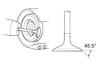
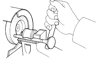
Inspect the valve face angle.
-
Grind the valve enough to remove pits and carbon.
-
Check that the valve is ground to the correct valve face angle.
Standard valve face angle 45.5°
-
-
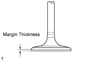
Inspect the valve head margin thickness.
-
Using a vernier caliper, measure the valve head margin thickness.
Standard margin thickness 1.0 mm (0.0394 in.) Minimum margin thickness 0.5 mm (0.0197 in.) If the margin thickness is less than the minimum, replace the valve.
-
-
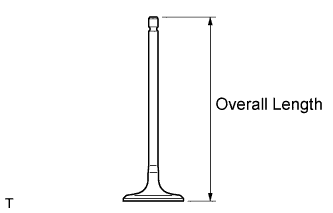
Inspect the valve overall length.
-
Using a vernier caliper, measure the overall length.
Standard Overall Length Item Specified Condition Intake 104.4 mm (4.11 in.) Exhaust 104.1 mm (4.10 in.) Minimum Overall Length Item Specified Condition Intake 104.1 mm (4.10 in.) Exhaust 103.8 mm (4.09 in.) If the overall length is less than the minimum, replace the valve.
-
-
Inspect the valve stem tip.
-
Check the surface of the valve stem tip for wear.
Note
Do not grind the valve so it becomes shorter than the minimum overall length.
If the valve stem tip is worn, resurface the tip with a grinder or replace the valve.
-
-
-
INSPECT VALVE GUIDE BUSH OIL CLEARANCE
-
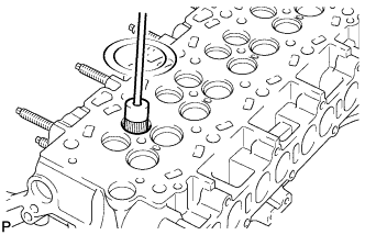
Using a caliper gauge, measure the inside diameter of the guide bush.
Standard bush inside diameter 6.01 to 6.03 mm (0.2366 to 0.2374 in.) -
Subtract the valve stem diameter measurement from the guide bush inside diameter measurement.
Standard Oil Clearance Item Specified Condition Intake 0.025 to 0.060 mm (0.000984 to 0.00236 in.) Exhaust 0.035 to 0.070 mm (0.00138 to 0.00276 in.) Maximum Oil Clearance Item Specified Condition Intake 0.120 mm (0.00472 in.) Exhaust 0.130 mm (0.00512 in.) If the oil clearance is more than the maximum, replace the valve guide bush.
-
-
CLEAN CYLINDER HEAD SUB-ASSEMBLY
-
Using a gasket scraper, remove all the gasket material from the cylinder block contact surface.
Note
Be careful not to scratch the cylinder block contact surface.
-
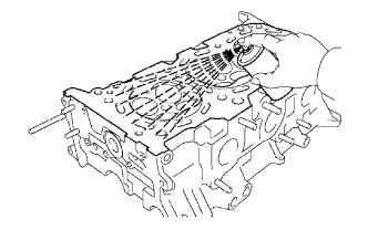
Using a wire brush, remove all the carbon from the combustion chambers.
Note
Be careful not to damage the combustion chambers and valve seats.
-
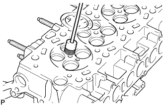
Using a valve guide bushing brush and solvent, clean all the valve guide bushes.
-
Using a soft brush and solvent, thoroughly clean the cylinder head.
-
-
INSPECT CYLINDER HEAD SUB-ASSEMBLY
-
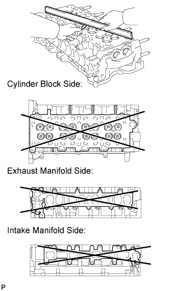
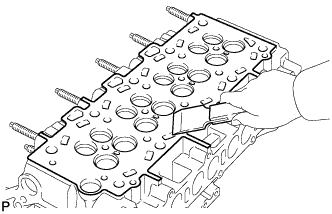
Using a precision straightedge and feeler gauge, measure the warpage of the contact surface between the cylinder head and cylinder block, and the cylinder head and manifolds.
Standard Warpage Item Specified Condition Cylinder block side 0 to 0.05 mm (0 to 0.00197 in.) Intake manifold side 0 to 0.08 mm (0 to 0.00315 in.) Exhaust manifold side 0 to 0.08 mm (0 to 0.00315 in.) Maximum Warpage Item Specified Condition Cylinder block side 0.05 mm (0.00197 in.) Intake manifold side 0.08 mm (0.00315 in.) Exhaust manifold side 0.08 mm (0.00315 in.) If the warpage is more than the maximum, replace the cylinder head sub-assembly.
-
Using a dye penetrant, check the intake ports, exhaust ports and cylinder surface for cracks.
If there are cracks, replace the cylinder head sub-assembly.
-
-
CLEAN VALVE SEAT
-
Using a 45° carbide cutter, resurface the valve seats.
Note
Be careful not to damage the combustion chambers and valve seats.
-
Clean the valve seats.
-
-
INSPECT INTAKE VALVE SEAT
-
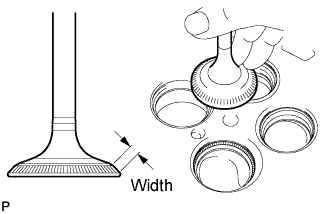
Apply a light coat of Prussian blue to the valve face.
-
Lightly press the valve face against the valve seat.
Note
Do not rotate the valve while pressing the valve.
-
Check the valve face and valve seat.
-
Check that the contact surfaces of the valve seat and valve face are in the middle area of their respective surfaces, with the width between 1.0 to 1.4 mm (0.0394 to 0.0551 in.).
If not, correct the valve seat.
-
Check that the contact surfaces of the valve seat and valve face are even around the entire valve seat.
If not, correct the valve seat.
-
-
-
INSPECT EXHAUST VALVE SEAT
-
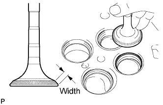
Apply a light coat of Prussian blue to the valve face.
-
Lightly press the valve face against the valve seat.
Note
Do not rotate the valve while pressing the valve.
-
Check the valve face and valve seat.
-
Check that the contact surfaces of the valve seat and valve face are in the middle area of their respective surfaces, with the width between 1.0 to 1.4 mm (0.0394 to 0.0551 in.).
If not, correct the valve seat.
-
Check that the contact surfaces of the valve seat and valve face are even around the entire valve seat.
If not, correct the valve seat.
-
-