w/ DPF:
When fuel lines are disconnected, air may enter the fuel lines, leading to engine starting trouble. Therefore, perform forced regeneration and bleed the air from the fuel lines.
- Click here
RECOVER REFRIGERANT FROM REFRIGERATION SYSTEM
-
Start the engine.
-
Turn the A/C switch on.
-
Operate the cooler compressor while the engine speed is approximately 1000 rpm for 5 to 6 minutes to circulate the refrigerant and collect the compressor oil remaining in each component into the cooler compressor.
-
Stop the engine.
-
Recover the refrigerant from the A/C system using a refrigerant recovery unit.
-
- Click here
PRECAUTION
Note:After turning the ignition switch off, waiting time may be required before disconnecting the cable from the battery terminal. Therefore, make sure to read the disconnecting the cable from the battery terminal notice before proceeding with work (Click here).
- Click here
DISCONNECT CABLE FROM NEGATIVE BATTERY TERMINAL
Note:When disconnecting the cable some systems need to be initialized after the cable is reconnected (Click here).
- Click here
REMOVE COWL TOP VENTILATOR LOUVER SUB-ASSEMBLY
- Click here
REMOVE NO. 1 ENGINE COVER SUB-ASSEMBLY (w/ Intercooler)
-
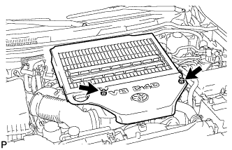
Remove the 2 nuts and No. 1 engine cover.
-
- Click here
REMOVE UPPER RADIATOR SUPPORT SEAL
-
Remove the 7 clips and upper radiator support seal.
-
- Click here
REMOVE MAIN BATTERY
- Click here
REMOVE SUB-BATTERY
- Click here
REMOVE FRONT WHEEL
- Click here
REMOVE HOOD SUB-ASSEMBLY
-
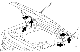
Remove the 2 hood stay bolts. Then disconnect the 2 hood supports.
Note:
-
Avoid touching the stroke portions of the rod as much as possible to prevent foreign matter from attaching to it. Be sure to hold the cylinders while servicing.
-
Do not wear cotton gloves or other similar materials when handling the rod. Fibers may attach to the rod and result in gas leaks.
-
Do not apply any load to the cylinders in the horizontal direction in order to prevent the rod from being deformed.
-
Remove the hood support while supporting the hood by hand.
-
-
Remove the 4 bolts and hood.
-
- Click here
REMOVE FRONT FENDER SPLASH SHIELD SUB-ASSEMBLY LH
-
Remove the 3 bolts and screw.
-
Loosen the clip and remove the front fender splash shield LH.
-
- Click here
REMOVE FRONT FENDER SPLASH SHIELD SUB-ASSEMBLY RH
-
Remove the 3 bolts and 2 screws.
-
Loosen the clip and remove the front fender splash shield RH.
-
- Click here
REMOVE NO. 1 ENGINE UNDER COVER SUB-ASSEMBLY
-
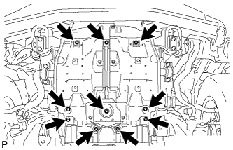
Remove the 10 bolts and No. 1 engine under cover.
-
- Click here
REMOVE NO. 2 ENGINE UNDER COVER
-
Remove the 2 bolts and No. 2 engine under cover.
-
-
Click here
REMOVE OIL PAN PROTECTOR ASSEMBLY
-
Remove the 4 bolts and oil pan protector.
-
- Click here
DRAIN ENGINE COOLANT
CAUTION:Do not remove the radiator reservoir cap while the engine and radiator are still hot. Pressurized, hot engine coolant and steam may be released and cause serious burns.
Tip:Collect the coolant in a container and dispose of it according to the regulations in your area.
-
Loosen the radiator drain cock plug.
-
Remove the radiator reservoir cap to drain the coolant in the radiator.
-
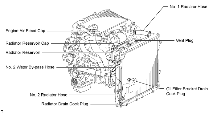
Loosen the oil filter bracket drain cock plug to drain the coolant in the engine.
-
Tighten the radiator drain cock plug by hand.
-
Tighten the oil filter bracket drain cock plug.
13 N*m 133 kgf*cm 10 ft.*lbf
-
- Click here
DRAIN ENGINE OIL
-
Remove the oil filler cap.
-
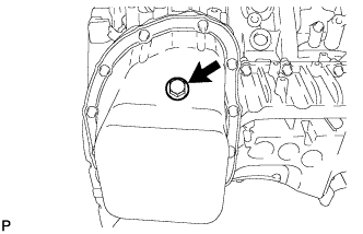
Remove the oil pan drain plug and gasket, and then drain the engine oil into a container.
-
Install a new gasket and the oil pan drain plug.
38 N*m 387 kgf*cm 28 ft.*lbf
-
- Click here
REMOVE INTERCOOLER ASSEMBLY (w/ Intercooler)
- Click here
REMOVE NO. 3 ENGINE ROOM WIRE
-
Disconnect the 4 wire harness clamps.
-
Remove the 2 nuts and No. 3 engine room wire.
-
- Click here
REMOVE AIR CLEANER CAP SUB-ASSEMBLY
-
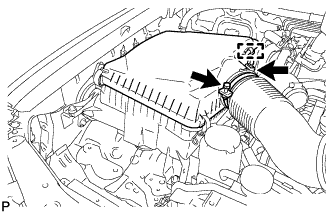
Loosen the hose clamp.
-
Disconnect the mass air flow meter connector and using a clip remover, detach the wire harness clamp from the air cleaner cap.
-
Detach the 4 clamps and remove the air cleaner cap.
-
- Click here
REMOVE AIR CLEANER FILTER ELEMENT
- Click here
REMOVE AIR CLEANER CASE
-
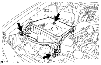
Using a clip remover, detach the wire harness clamp.
-
Remove the 3 bolts and air cleaner case.
-
- Click here
REMOVE NO. 1 AIR CLEANER HOSE
-
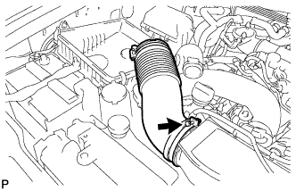
Loosen the hose clamp and remove the No. 1 air cleaner hose.
-
- Click here
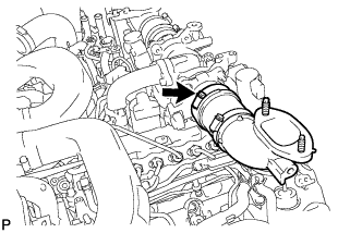
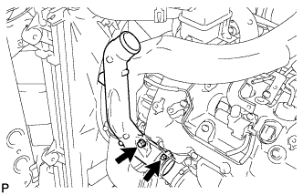
REMOVE INTAKE AIR CONNECTOR
-
w/ Viscous Heater:
Disconnect the 2 connectors from the viscous with magnet clutch heater and water temperature sensor.
Table 1. Text in Illustration *A w/ Viscous Heater -
w/o Viscous Heater:
Disconnect the connector from the water temperature sensor.
-
Using a clip remover, detach the 3 wire harness clamps.
-
Loosen the 2 hose clamps and remove the 2 bolts and intake air connector.
-
- Click here
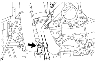
REMOVE VANE PUMP OIL RESERVOIR ASSEMBLY
-
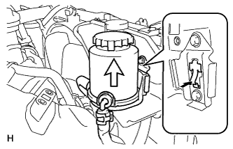
Insert a screwdriver between the reservoir and oil reservoir bracket, push the claw, and then disconnect the reservoir by pulling it upwards.
-
- Click here
REMOVE NO. 1 OIL RESERVOIR BRACKET
-
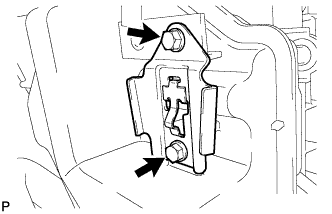
Remove the 2 bolts and bracket.
-
- Click here
REMOVE RADIATOR RESERVOIR ASSEMBLY
-
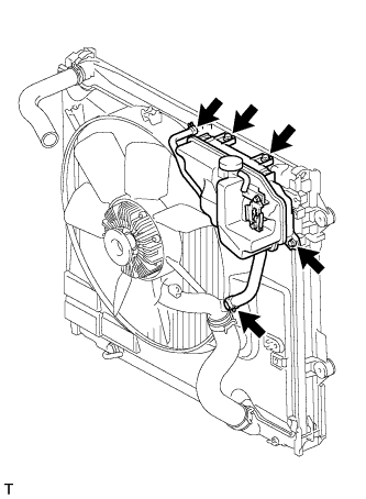
Disconnect the 2 hoses.
-
Remove the 3 bolts and radiator reservoir.
-
- Click here
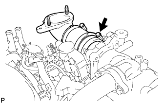
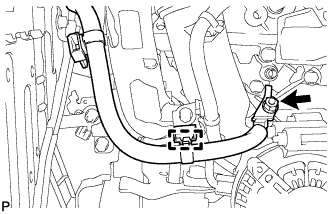
REMOVE VANE PUMP ASSEMBLY
-
w/ DPF: (Click here)
-
w/o DPF: (Click here)
-
- Click here
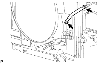
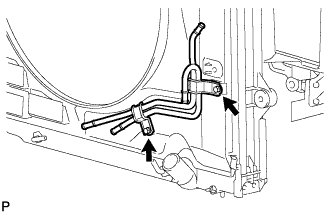
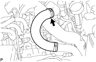
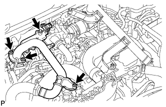
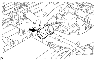
DISCONNECT NO. 1 RADIATOR HOSE
- Click here
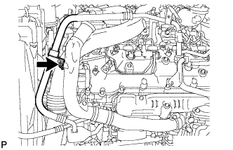
DISCONNECT NO. 2 RADIATOR HOSE
- Click here
REMOVE V-RIBBED BELT (w/ Viscous Heater)
-
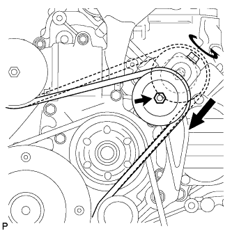
Loosen the lock nut and turn the bolt counterclockwise.
-
Remove the V-ribbed belt.
-
- Click here
REMOVE NO. 1 IDLER PULLEY (w/ Viscous Heater)
-
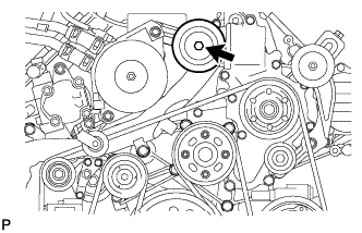
Remove the bolt, cover, No. 1 idler pulley and collar.
-
- Click here
REMOVE NO. 3 IDLER PULLEY (w/ Viscous Heater)
-
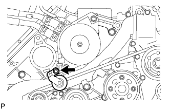
Remove the nut and No. 3 idler pulley.
-
- Click here
REMOVE V-RIBBED BELT
-
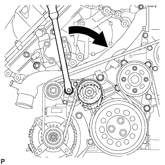
Using a wrench to the V-ribbed belt tensioner bracket, turn the wrench clockwise and remove the V-ribbed belt.
-
- Click here
REMOVE FRONT FENDER APRON SEAL FRONT RH
-
Remove the 3 clips and front fender apron seal front RH.
-
- Click here
REMOVE FRONT FENDER APRON SEAL REAR RH
-
Remove the 4 clips and front fender apron seal rear RH.
-
- Click here
REMOVE FRONT FENDER APRON SEAL FRONT LH
-
w/o KDSS:
Remove the 4 clips and front fender apron seal front LH.
-
w/ KDSS:
Remove the 3 clips and front fender apron seal front LH.
-
- Click here
REMOVE FRONT FENDER APRON SEAL REAR LH
-
Remove the 4 clips and front fender apron seal rear LH.
-
- Click here
REMOVE OIL COOLER TUBE (for Automatic Transmission)
-
Disconnect the inlet and outlet No. 1 oil cooler hose.
-
Disconnect the inlet No. 2 and No. 3 oil cooler hoses.
-
Disconnect the inlet No. 4 oil cooler hose.
-
Remove the 2 bolts and transmission oil cooler tube.
-
- Click here
REMOVE FAN SHROUD WITH FAN
-
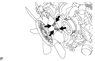
Loosen the 4 nuts holding the fluid coupling fan.
-
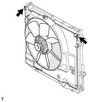
Remove the 2 bolts holding the fan shroud.
-
Remove the 4 nuts of the fluid coupling fan, and then remove the shroud together with the fluid coupling fan.
-
- Click here
REMOVE FAN PULLEY
- Click here
REMOVE FRONT BUMPER WINCH COVER (w/ Winch)
-
Detach the 2 claws.
-
Detach the 3 guides and remove front bumper winch cover sub-assembly.
-
- Click here
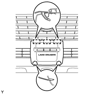
REMOVE RADIATOR GRILLE
-

Put protective tape around the radiator grille assembly.
Table 2. Text in Illustration *1 Protective Tape -
Remove the 3 screws.
-
Detach the 2 clips and 8 claws, and remove the radiator grille assembly.
-
w/ Wide View Front Monitor System:
-
Disconnect the connector.
-
-
- Click here
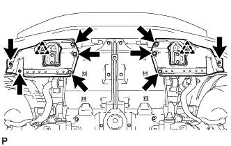
REMOVE FRONT BUMPER COVER
Tip:For the front bumper cover with garnish, use the procedure described below.
-
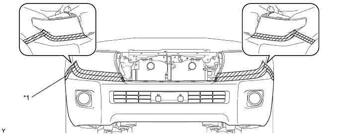
Put protective tape around the front bumper cover.
Table 3. Text in Illustration *1 Protective Tape - - -
Using a T30 "TORX" socket, remove the 6 screws.
Table 4. Text in Illustration *A LH Side *B RH Side -
Remove the 3 clips, 4 screws and 4 bolts.
-
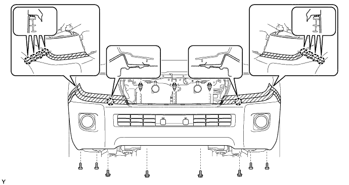
Detach the 10 claws and remove the front bumper cover.
-
w/ TOYOTA Parking Assist-sensor System or w/ Fog Light:
Disconnect the No. 4 engine room wire connector and remove the front bumper cover.
-
w/ Headlight Cleaner System:
Disconnect the headlight cleaner hose and remove the front bumper cover.
-
- Click here
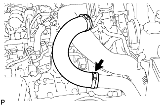
REMOVE TRANSMISSION OIL COOLER AIR DUCT (for Automatic Transmission)
-
Remove the 4 bolts and oil cooler air duct.
-
- Click here
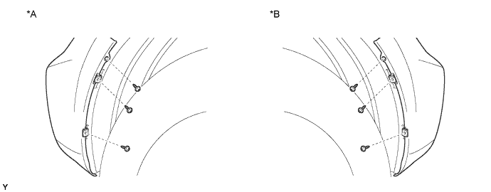
DISCONNECT RADIATOR SIDE DEFLECTOR RH (for Manual Transmission)
-
Using a clip remover, remove the 4 clips, and remove the side deflector.
-
- Click here
DISCONNECT RADIATOR SIDE DEFLECTOR LH
-
Using a clip remover, remove the 4 clips, and remove the side deflector.
-
- Click here
REMOVE RADIATOR ASSEMBLY
-
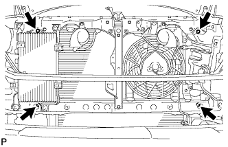
Remove the 4 bolts and radiator.
-
-
Click here
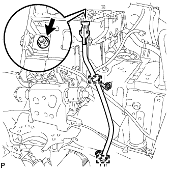
DISCONNECT FRONT DIFFERENTIAL BREATHER TUBE
- Click here
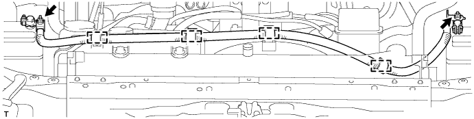
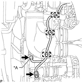
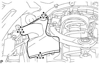
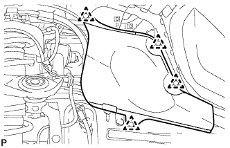
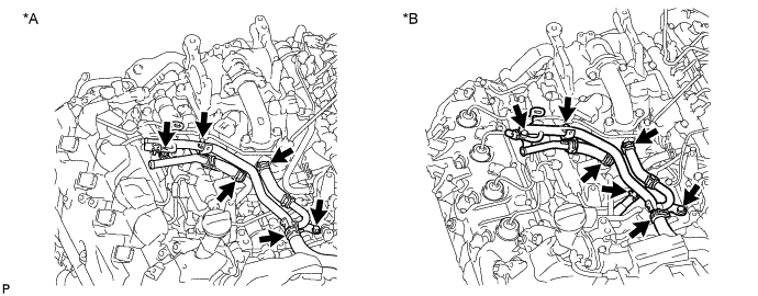
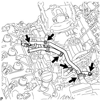
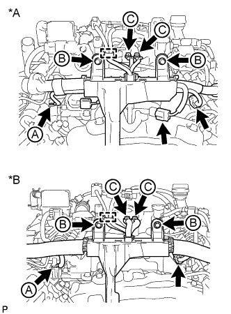
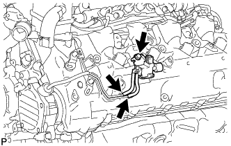
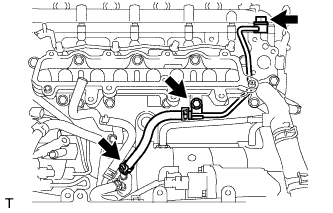
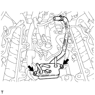
DISCONNECT FUEL TUBE
-
w/ DPF:
Disconnect the 2 fuel tubes from the No. 1 and No. 3 fuel tube clamps.
-
w/o DPF:
Disconnect the 3 fuel tubes from the No. 1 and No. 3 fuel tube clamps.
-
- Click here
REMOVE NO. 1 COOL AIR INLET (w/o Intercooler)
-
Loosen the No. 1 air hose clamp.
-
Disconnect the turbo pressure sensor connector, intake air temperature sensor connector and vacuum hose.
-
Remove the 3 nuts, bolt and No. 1 cool air inlet.
-
Remove the gasket from the air tube RH.
-
- Click here
REMOVE NO. 2 COOL AIR INLET (w/o Intercooler)
-
Loosen the No. 2 air hose clamp.
-
Remove the 3 nuts, bolt and No. 2 cool air inlet.
-
Remove the gasket from the air tube LH.
-
-
Click here
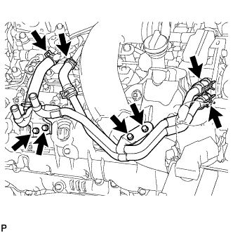
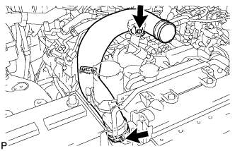
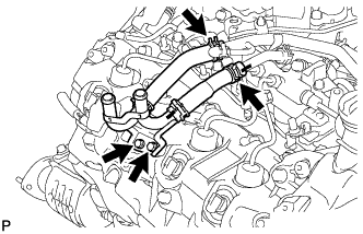
DISCONNECT WATER HOSE SUB-ASSEMBLY
Table 5. Text in Illustration *A w/ Rear Heater *B w/o Rear Heater - Click here
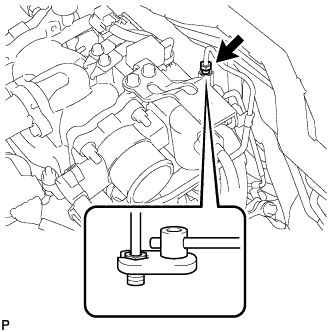
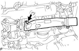
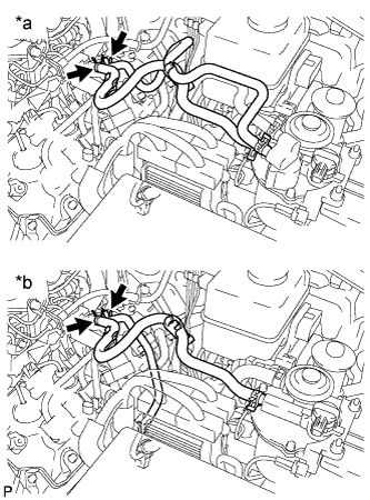
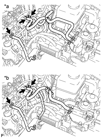
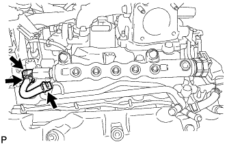
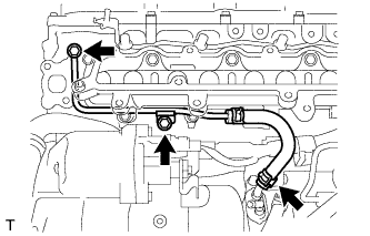
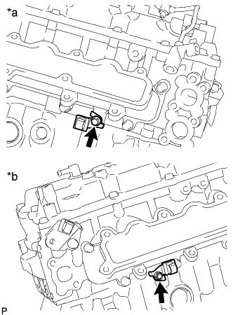
REMOVE NO. 2 ENGINE OIL LEVEL DIPSTICK GUIDE
-
Disconnect the wire harness clamp from the No. 2 engine oil level dipstick guide.
-
Disconnect the ventilation hose from the cylinder head cover RH.
Table 6. Text in Illustration *A w/ DPF *B w/o DPF -
Remove the 2 bolts and No. 2 engine oil level dipstick guide.
-
Remove the O-ring from the No. 2 engine oil level dipstick guide.
-
- Click here
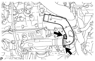
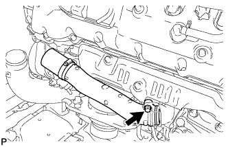
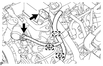
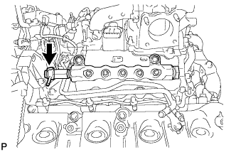
REMOVE AIR TUBE SUB-ASSEMBLY RH
-
Loosen the hose clamp.
-
Remove the air tube from the throttle body.
-
- Click here
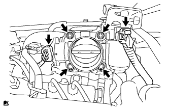
REMOVE DIESEL THROTTLE BODY ASSEMBLY RH
-
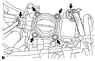
Disconnect the throttle position sensor connector.
-
Disconnect the throttle motor connector.
-
Remove the 2 bolts, 2 nuts and throttle body.
-
Remove the gasket from the intake pipe.
-
- Click here
DRAIN CLUTCH FLUID (for Manual Transmission)
- Click here
REMOVE CLUTCH HOSE (for Manual Transmission)
-
Disconnect the 2 flexible hose tubes from the clutch hose with a 10 mm union nut wrench while holding the flexible hose with a wrench.
Note:
-
Do not bend or damage the flexible hose tubes.
-
Do not allow any foreign matter such as dirt and dust to enter the flexible hose tubes from the connecting point.
-
-
Remove the 2 clips.
-
Remove the bolt and clutch hose.
-
- Click here
REMOVE AIR TUBE SUB-ASSEMBLY LH
-
Loosen the hose clamp.
-
Remove the air tube from the throttle body.
-
- Click here
REMOVE TUBE CONNECTOR TO FLEXIBLE HOSE TUBE (for Manual Transmission)
-
Using a 10 mm union nut wrench, disconnect the tube connector to flexible hose tube from the clutch tube to release cylinder 2 way.
Note:
-
Do not bend or damage the flexible hose tube.
-
Do not allow any foreign matter such as dirt and dust to enter the flexible hose tube from the connecting point.
-
-
Remove the 2 bolts and tube connector to flexible hose tube.
-
- Click here
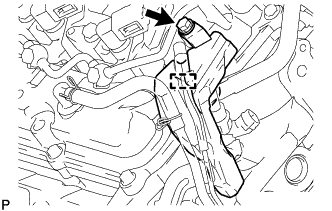
REMOVE NO. 1 GAS FILTER
-
Disconnect the hose from the intake pipe.
-
Remove the No. 1 gas filter.
-
- Click here
REMOVE NO. 3 INTERCOOLER SUPPORT BRACKET
-
for Manual Transmission:
-
Remove the bolt and disconnect the clutch tube to release cylinder 2 way from the No. 3 intercooler support bracket.
-
-
Remove the 2 bolts and No. 3 intercooler support bracket.
-
- Click here
REMOVE DIESEL THROTTLE BODY ASSEMBLY LH
-
Disconnect the throttle position sensor connector.
-
Disconnect the throttle motor connector.
-
Remove the 2 bolts, 2 nuts and throttle body.
-
Remove the gasket from the intake pipe.
-
- Click here
REMOVE NO. 1 AIR HOSE
-
Loosen the hose clamp and remove the No. 1 air hose.
-
- Click here
REMOVE NO. 3 AIR TUBE
-
Disconnect the wire harness from the clamp.
-
Remove the nut and ground wire.
-
Remove the bolt and disconnect the wire harness bracket.
-
Loosen the hose clamp and remove the bolt and No. 3 air tube.
-
- Click here
REMOVE NO. 1 AIR TUBE ASSEMBLY
-
Remove the bolt and No. 1 air tube.
-
Remove the O-ring.
-
- Click here
REMOVE NO. 2 AIR HOSE
-
Loosen the hose clamp and remove the No. 2 air hose.
-
- Click here
REMOVE NO. 4 AIR TUBE
-
Remove the bolt and disconnect the suction hose.
-
Loosen the hose clamp and remove the bolt and No. 4 air tube.
-
- Click here
REMOVE NO. 2 AIR TUBE ASSEMBLY
-
Remove the bolt and No. 2 air tube.
-
Remove the O-ring.
-
- Click here
REMOVE NO. 2 AIR CLEANER PIPE SUB-ASSEMBLY
-
Disconnect the ventilation hose from the oil separator.
-
Loosen the hose clamp.
-
Remove the bolt and No. 2 air cleaner pipe.
-
- Click here
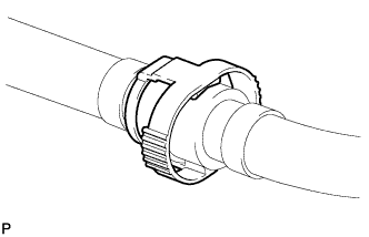
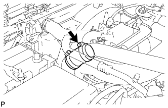
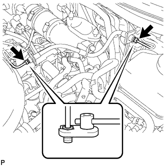
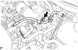
REMOVE NO. 1 COOLER REFRIGERANT DISCHARGE HOSE
-
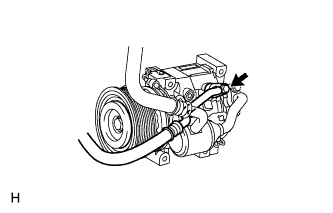
Remove the bolt and disconnect the discharge hose from the cooler compressor.
-
Remove the O-ring from the discharge hose.
Note:Seal the openings of the disconnected parts using vinyl tape to prevent moisture and foreign matter from entering them.
-
- Click here
REMOVE SUCTION HOSE SUB-ASSEMBLY
-
Remove the bolt and disconnect the suction hose from the cooler compressor.
-
Remove the O-ring from the suction hose.
Note:Seal the openings of the disconnected parts using vinyl tape to prevent moisture and foreign matter from entering them.
-
- Click here
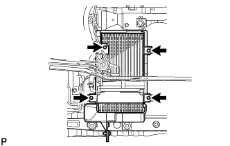
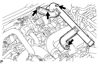
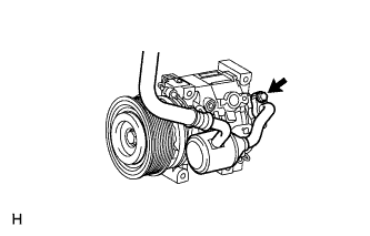
REMOVE COOLER COMPRESSOR ASSEMBLY
-
Disconnect the 4 connectors.
-
Using a clip remover, detach the 3 wire harness clamps.
-
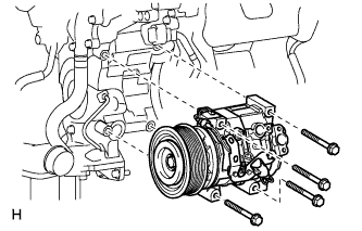
Remove the 4 bolts and cooler compressor.
-
- Click here
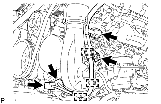
REMOVE NO. 2 INTAKE AIR CONNECTOR PIPE
-
w/ Intercooler:
Disconnect the vacuum hose.
-
Loosen the hose clamp, and remove the bolt and No. 2 intake air connector pipe.
-
- Click here
REMOVE HEATER WATER PIPE SUB-ASSEMBLY (w/ Viscous Heater)
-
Remove the 4 bolts and disconnect the 4 water hose ends, and then remove the heater water pipe.
-
- Click here
REMOVE NO. 1 AIR CLEANER PIPE SUB-ASSEMBLY
-
Loosen the hose clamp.
-
Remove the bolt and No. 1 air cleaner pipe.
-
- Click here
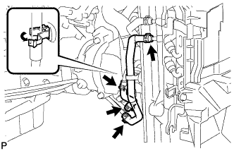
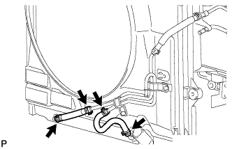
DISCONNECT FUEL HOSE
-
w/ DPF:
Table 7. Text in Illustration *a for Fuel Filter with Heater *b for Fuel Filter without Heater -
w/o DPF:
Table 8. Text in Illustration *a for Fuel Filter with Heater *b for Fuel Filter without Heater
-
- Click here
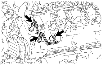
REMOVE NO. 3 WATER BY-PASS PIPE (w/o Viscous Heater)
-
Remove the 2 bolts and disconnect the 2 water hose ends, and then remove the No. 3 water by-pass pipe.
-
- Click here
REMOVE NO. 4 WATER BY-PASS PIPE
-
w/ EGR System:
-
Remove the 2 bolts and nut.
Table 9. Text in Illustration *A w/ DPF *B w/o DPF -
w/ DPF:
Disconnect the 3 water hose ends, and then remove the No. 4 water by-pass pipe.
-
w/o DPF:
Disconnect the 4 water hose ends, and then remove the No. 4 water by-pass pipe.
-
-
w/o EGR System:
-
Remove the 2 bolts and nut.
-
Disconnect the 3 water hose ends, and then remove the No. 4 water by-pass pipe.
-
-
- Click here
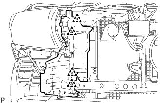
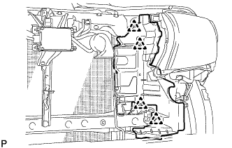
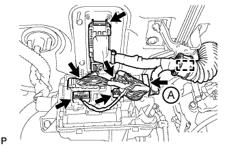
DISCONNECT ENGINE WIRE
-
LH Side:
-
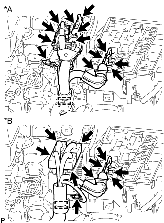
w/ DPF:
Disconnect the 7 connectors from the injector driver.
Table 10. Text in Illustration *A w/ DPF *B w/o DPF -
w/o DPF:
Disconnect the 4 connectors from the injector driver.
-
Disconnect the 4 connectors and detach the wire harness holder from the relay block.
-
Remove the bolt and disconnect the ground wire.
-
Disconnect the wire harness from the wire harness clamp holder.
-
Remove the bolt and disconnect the ground wire from the body panel.
-
Using a clip remover, detach the ground wire clamp labeled A from the relay block side.
-
Disconnect the wire harness from the wire harness clamp holder labeled B.
-
Remove the nut and detach the generator positive (+) cable holder from the relay block.
-
Disconnect the generator positive (+) cable from the 2 clamps.
-
Disconnect the 2 connectors.
-
Using a clip remover, detach the 3 wire harness clamps.
-
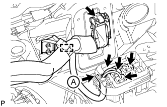
for RHD:
Disconnect the 4 connectors and detach the wire harness tab labeled A from the relay block.
-
for RHD:
Disconnect the ECM connector.
-
for RHD:
Disconnect the wire harness from the wire harness clamp holder.
-
Disconnect the 8 connectors.
Table 11. Text in Illustration *A w/ DPF *B w/o DPF -
Remove the bolt and the engine wire harness bracket labeled B.
-
Using a clip remover, detach the wire harness clamp labeled D.
-
Remove the 2 bolts and disconnect the engine wire protector labeled A.
-
for RHD:
Disconnect the wire harness from the wire harness clamp holder labeled C.
-
-
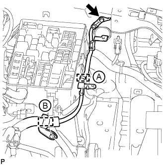
RH Side:
-
for LHD:
Disconnect the 4 connectors, and detach the wire harness holder from the relay block labeled A.
-
for LHD:
Disconnect the ECM connector.
-
for LHD:
Disconnect the wire harness from the wire harness clamp holder.
-
Disconnect the 7 connectors.
Table 12. Text in Illustration *A w/ DPF *B w/o DPF -
Using a clip remover, detach the wire harness clamp.
-
Remove the 3 bolts and disconnect the engine wire protector labeled A.
-
Remove the bolt and the wire harness bracket labeled B.
-
Remove the screw grommet, nut and the glow plug wire harness labeled C.
-
for RHD:
Disconnect the wire harness from the wire harness clamp holder.
Table 13. Text in Illustration *A w/ DPF *B w/o DPF -
for RHD:
Remove the bolt and wire harness clamp holder.
-
w/ Winch:
Remove the bolt and disconnect the ground wire.
-
-
Rear Side:
-
Using a clip remover, detach the wire harness clamp.
Table 14. Text in Illustration *A w/ DPF *B w/o DPF -
Remove the 2 bolts and 2 ground wires labeled C.
-
Remove the 2 bolts and disconnect the engine wire harness protector labeled B.
-
w/ DPF:
Disconnect the 3 connectors.
-
w/o DPF:
Disconnect the connector.
-
Remove the screw grommet, nut and disconnect the glow plug wire harness labeled A.
-
-
- Click here
REMOVE NO. 2 FUEL PIPE SUB-ASSEMBLY (w/o DPF)
Note:
-
After removing a fuel pipe, to prevent dirt or foreign objects from entering the fuel pipe ends, cover the fuel pipe ends with plastic bags.
-
After removing a fuel pipe, to prevent dirt or foreign objects from entering the fuel supply pump hole, cover the hole with protective tape.
-
Disconnect the fuel hose from the No. 5 nozzle leakage pipe.
-
Remove the bolt and No. 2 injection pipe clamp.
-
Remove the union bolt and gasket.
-
Remove the bolt, nut and No. 2 fuel pipe.
-
- Click here
REMOVE NO. 6 INJECTION PIPE SUB-ASSEMBLY
Note:After removing an injection pipe, to prevent dirt or foreign objects from entering the common rail holes, cover the holes with protective tape.
-
w/ EGR System:
-
Using a union nut wrench, loosen the No. 6 injection pipe ends.
-
Remove the 2 nuts and 2 No. 2 injection pipe clamps.
-
Remove the No. 6 injection pipe.
-
-
w/o EGR System:
-
Using a union nut wrench, loosen the No. 6 injection pipe ends.
-
Remove the nut and No. 2 injection pipe clamp.
-
Remove the bolt and No. 6 injection pipe.
-
-
- Click here
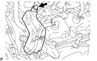
REMOVE NO. 1 VACUUM SWITCHING VALVE ASSEMBLY (w/ DPF)
-
Disconnect the 2 vacuum hoses.
-
Remove the bolt and vacuum switching valve.
-
- Click here
REMOVE NO. 1 VACUUM TRANSMITTING PIPE SUB-ASSEMBLY (w/ DPF)
-
Disconnect the 2 vacuum hoses.
-
Remove the 3 bolts and vacuum transmitting pipe.
-
- Click here
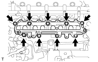
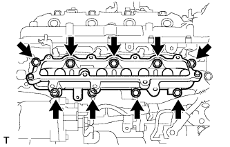
REMOVE CYLINDER HEAD COVER SILENCER LH (w/ DPF)
-
Remove the 4 bolts and cylinder head cover silencer.
-
- Click here
REMOVE NO. 4 NOZZLE LEAKAGE PIPE (w/ DPF)
-
Disconnect the fuel hose.
-
Remove the fuel check valve, No. 4 nozzle leakage pipe and gasket.
-
- Click here
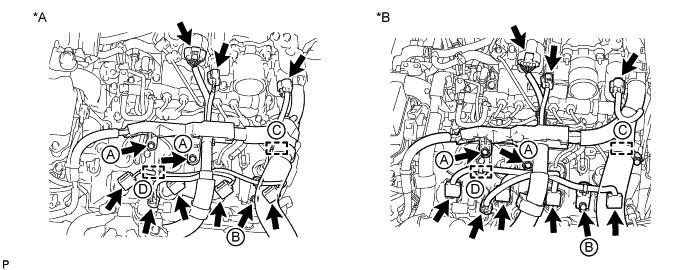
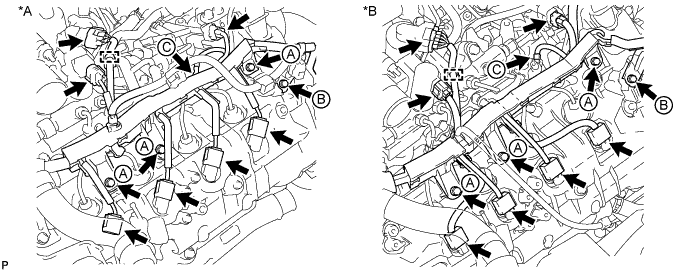
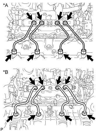
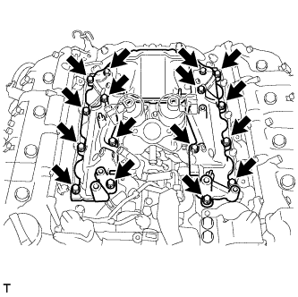
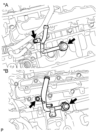
REMOVE INJECTION PIPE LH
-
w/ Intercooler:
Remove the 2 nuts and 4 injection pipe clamps.
Table 15. Text in Illustration *A w/ DPF *B w/o DPF -
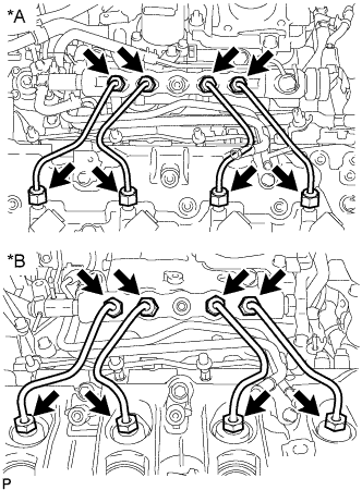
Using a union nut wrench, remove the 4 injection pipes.
Table 16. Text in Illustration *A w/ DPF *B w/o DPF Note:After removing an injection pipe, to prevent dirt or foreign objects from entering the common rail holes or injector holes, cover the holes with protective tape.
-
- Click here
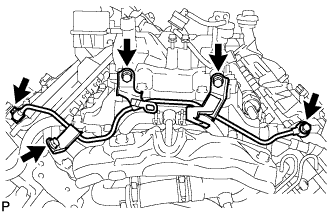
REMOVE NO. 2 FUEL PIPE (w/ DPF)
-
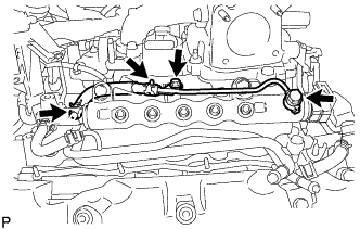
Remove the No. 4 fuel hose.
-
Remove the union bolt, gasket, bolt, and No. 2 fuel pipe.
-
- Click here
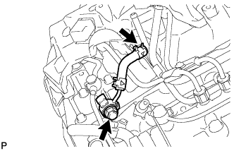
REMOVE NO. 5 NOZZLE LEAKAGE PIPE (w/ DPF)
-
w/ DPF:
-
Disconnect the fuel hose.
-
Remove the union bolt, gasket and No. 5 nozzle leakage pipe.
-
-
w/o DPF:
Remove the union bolt, gasket and No. 5 nozzle leakage pipe.
-
- Click here
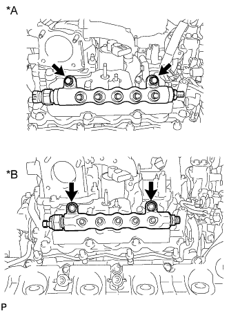
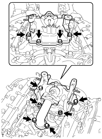
REMOVE COMMON RAIL ASSEMBLY LH
-
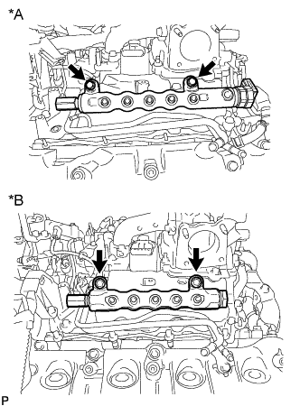
Remove the 2 bolts and common rail.
Table 17. Text in Illustration *A w/ DPF *B w/o DPF Note:
-
Do not remove the fuel pressure limiter from the common rail. If it is removed, replace the common rail.
-
w/ DPF:
Do not remove the pressure discharge valve from the common rail. If it is removed, replace the common rail.
-
-
- Click here
REMOVE FUEL FILTER TO INJECTION PUMP FUEL PIPE SUB-ASSEMBLY
-
w/ DPF:
-
Remove the bolt and No. 2 injection pipe clamp.
-
Disconnect the fuel hose.
-
Remove the union bolt, nut, bolt, fuel filter to injection pump fuel pipe and gasket.
-
-
w/o DPF:
-
Disconnect the 2 hoses from the fuel pipe.
-
Remove the bolt and fuel filter to injection pump fuel pipe.
-
-
- Click here
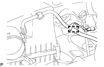
DISCONNECT FUEL PUMP MOTOR WIRE
-
Remove the bolt and disconnect the connector from the fuel supply pump.
-
- Click here
REMOVE NO. 5 INJECTION PIPE SUB-ASSEMBLY
-
Using a union nut wrench, remove the No. 5 injection pipe.
Note:After removing an injection pipe, to prevent dirt or foreign objects from entering the common rail hole or injection pump hole, cover the holes with protective tape.
-
- Click here
REMOVE CYLINDER HEAD COVER SILENCER RH (w/ DPF)
-
Remove the 4 bolts and cylinder head cover silencer.
-
- Click here
REMOVE INJECTION PIPE RH
-
w/ Intercooler:
Remove the 2 nuts and 4 injection pipe clamps.
Table 18. Text in Illustration *A w/ DPF *B w/o DPF -
Using a union nut wrench, remove the 4 injection pipes.
Table 19. Text in Illustration *A w/ DPF *B w/o DPF Note:After removing an injection pipe, to prevent dirt or foreign objects from entering the common rail holes or injector holes, cover the holes with protective tape.
-
- Click here
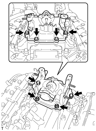
REMOVE COMMON RAIL ASSEMBLY RH
-
Remove the 2 bolts and common rail.
Table 20. Text in Illustration *A w/ DPF *B w/o DPF Note:Do not remove the fuel pressure sensor from the common rail. If it is removed, replace the common rail.
-
-
Click here
REMOVE NO. 1 INTAKE MANIFOLD INSULATOR (w/ Intercooler)
-
Click here
REMOVE NO. 2 INTAKE MANIFOLD INSULATOR (w/ Intercooler)
- Click here
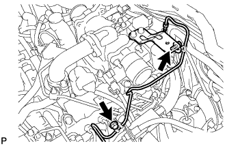
REMOVE CONNECTING WIRE (w/ DPF)
-
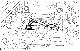
Detach the 2 clamps and remove the connecting wire.
-
- Click here
REMOVE NO. 3 NOZZLE LEAKAGE PIPE (w/ DPF)
-
Remove the 2 injector hollow screws, 3 bolts, No. 3 nozzle leakage pipe and 2 gaskets.
-
- Click here
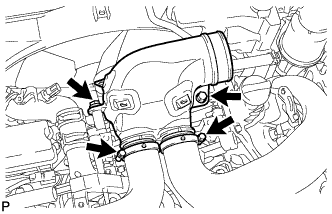
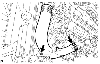
REMOVE INTAKE PIPE
-
w/ EGR System:
Remove the 2 nuts, 6 bolts, intake pipe and 2 gaskets.
-
w/o EGR System:
Remove the 2 nuts, 4 bolts, intake pipe and gasket.
-
- Click here
DISCONNECT NO. 2 ENGINE WIRE
-
Remove the 3 bolts and using a clip remover, detach the 2 wire harness clamps, and then disconnect the No. 2 engine wire.
-
- Click here
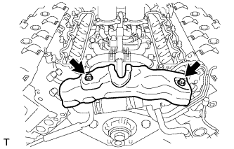
REMOVE NO. 3 INTAKE MANIFOLD
-
Remove the 16 bolts, No. 3 intake manifold and 2 gaskets.
-
-
Click here
REMOVE INTAKE MANIFOLD INSULATOR (w/ EGR System)
- Click here
REMOVE EGR PIPE INSULATOR (w/ EGR System)
-
Remove the 2 bolts and EGR pipe insulator.
-
- Click here
REMOVE EGR VALVE ASSEMBLY WITH EGR COOLER (w/ EGR System)
-
Remove the 10 bolts, EGR valve with EGR cooler and 2 gaskets.
-
Disconnect the No. 5 water by-pass hose from the water by-pass outlet.
-
-
Click here
REMOVE EGR COOLER INSULATOR (w/ EGR System)
- Click here
REMOVE NO. 3 NOZZLE LEAKAGE PIPE (w/o DPF)
-
Disconnect the No. 1 fuel hose from the fuel cooler.
-
Remove the union bolt, bolt, No. 3 nozzle leakage pipe and gasket.
Note:After removing the nozzle leakage pipe, to prevent dirt or foreign objects from entering the nozzle leakage pipe, cover the nozzle leakage pipe ends with plastic bags.
-
- Click here
REMOVE NO. 4 NOZZLE LEAKAGE PIPE (w/o DPF)
-
Disconnect the No. 2 fuel hose from the fuel cooler.
-
Remove the union bolt, bolt, No. 4 nozzle leakage pipe and gasket.
Note:After removing the nozzle leakage pipe, to prevent dirt or foreign objects from entering the nozzle leakage pipe, cover the nozzle leakage pipe ends with plastic bags.
-
-
Click here
DISCONNECT NO. 6 WATER BY-PASS HOSE (w/o DPF)
- Click here
REMOVE FUEL COOLER ASSEMBLY (w/o DPF)
-
Remove the 2 bolts and fuel cooler.
-
- Click here
REMOVE NO. 2 FUEL INJECTOR PROTECTOR (w/ DPF)
-
Detach the hose clamp.
-
Remove the bolt and No. 2 fuel injector protector.
-
- Click here
REMOVE NO. 1 FUEL INJECTOR PROTECTOR (w/ DPF)
-
Remove the bolt and No. 1 fuel injector protector.
-
- Click here
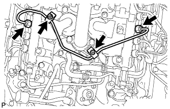
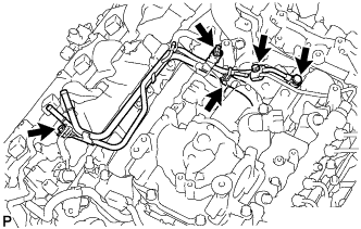
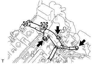
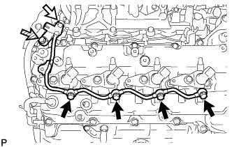
REMOVE FUEL TUBE SUB-ASSEMBLY (w/ DPF)
-
Disconnect the 3 fuel tube connectors (Click here).
-
Detach the 3 clamps and remove the fuel tube.
-
- Click here
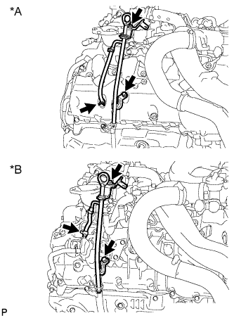
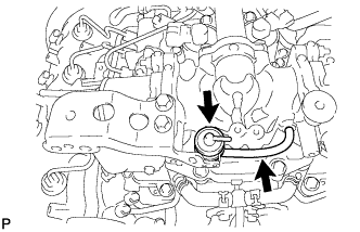
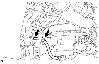
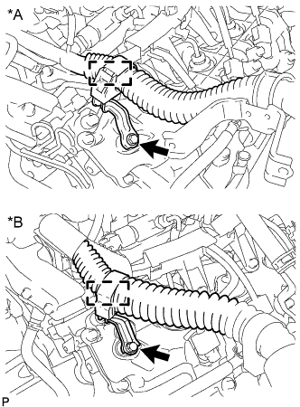
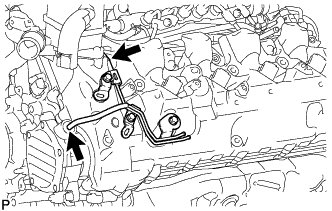
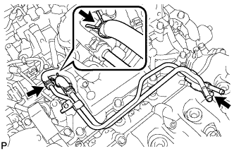
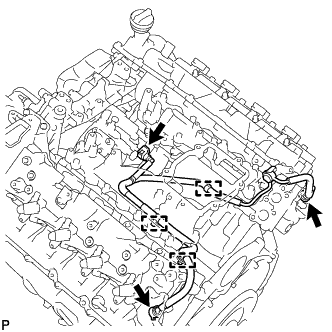
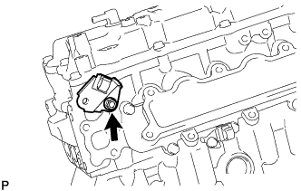
REMOVE NO. 1 WATER BY-PASS PIPE
-
Remove the union bolt, bolt, No. 1 water by-pass pipe and gasket.
Table 21. Text in Illustration *A w/ DPF *B w/o DPF
-
- Click here
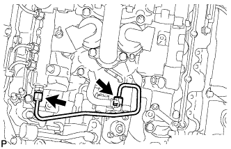
REMOVE NO. 2 NOZZLE LEAKAGE PIPE (w/ DPF)
-
Remove the 4 injector hollow screws and 4 gaskets.
Table 22. Text in Illustration 
Injector Hollow Screw 
Bolt -
Remove the 2 bolts and No. 2 nozzle leakage pipe.
Note:
-
When removing the nozzle leakage pipe, place a cushion under the pipe.
-
Be careful not to deform or scratch the union seal surface.
-
After removing the nozzle leakage pipe, put it in a plastic bag to prevent foreign matter from contaminating its injector inlet.
-
-
- Click here
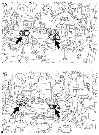
REMOVE NO. 1 NOZZLE LEAKAGE PIPE (w/ DPF)
-
Remove the 4 injector hollow screws and 4 gaskets.
Table 23. Text in Illustration Injector Hollow Screw No. 2 Check Valve 
Union Bolt -
Remove the No. 2 check valve from the fuel tube and No. 1 nozzle leakage pipe.
-
Remove the union bolt and No. 1 nozzle leakage pipe.
Note:
-
When removing the nozzle leakage pipe, place a cushion under the pipe.
-
Be careful not to deform or scratch the union seal surface.
-
After removing the nozzle leakage pipe, put it in a plastic bag to prevent foreign matter from contaminating its injector inlet.
-
-
- Click here
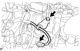
REMOVE FUEL HOSE BRACKET (w/ DPF)
-
Remove the bolt and fuel hose bracket.
-
- Click here
REMOVE NO. 1 FUEL PIPE CLAMP (w/ DPF)
-
Remove the 2 bolts and 2 No. 1 fuel pipe clamps.
Table 24. Text in Illustration *a RH Side *b LH Side
-
- Click here
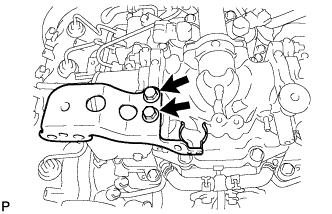
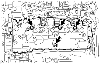
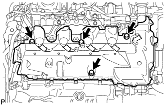
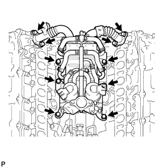
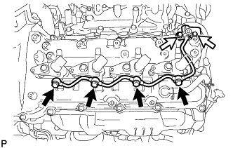
REMOVE NO. 1 INTAKE MANIFOLD
-
Remove the 9 bolts, No. 1 intake manifold and gasket.
-
- Click here
REMOVE NO. 2 INTAKE MANIFOLD
-
Remove the 9 bolts, No. 2 intake manifold and gasket.
-
- Click here
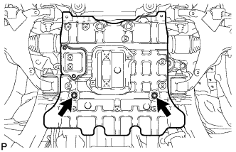
INSTALL NO. 1 AND NO. 2 ENGINE HANGER
-
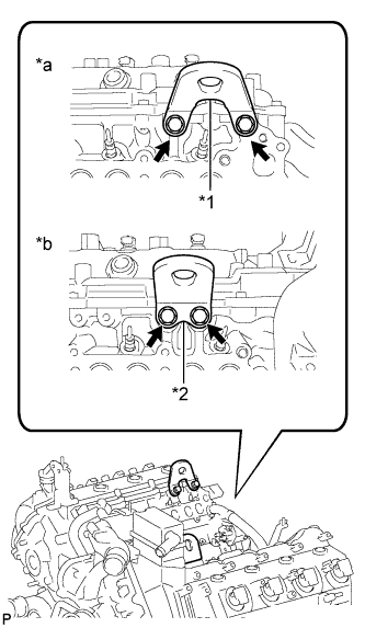
Install the No. 1 and No. 2 engine hangers to the cylinder head RH and LH with the 4 bolts as shown in the illustration.
25 N*m 250 kgf*cm 18 ft.*lbf Tip:No. 1 engine hanger 12281-51040 No. 2 engine hanger 12282-51040 Bolt 91671-80825 Table 25. Text in Illustration *1 No. 1 Engine Hanger *2 No. 2 Engine Hanger *a RH *b LH
-
- Click here
REMOVE AUTOMATIC TRANSMISSION ASSEMBLY
- Click here
REMOVE MANUAL TRANSMISSION UNIT ASSEMBLY
- Click here
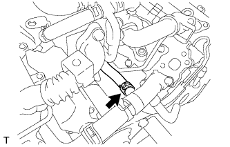
REMOVE CLUTCH RELEASE CYLINDER TO FLEXIBLE HOSE TUBE (for Manual Transmission)
-
Remove the bolt and clutch release cylinder to flexible hose tube.
-
- Click here
REMOVE ENGINE ASSEMBLY
-
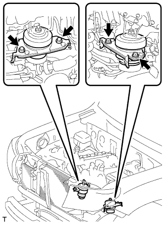
Attach an engine sling device and hang the engine with a chain block.
-
Remove the 4 bolts from the engine mounting RH and LH side.
-
Lift the engine out of the vehicle carefully.
Note:
-
Make sure the engine is clear of all wiring and hoses.
-
With the exception of installing the engine assembly to an engine stand or removing the engine assembly from an engine stand, do not perform any work on the engine while it is suspended, as doing so is dangerous.
-
Pay attention to the angle of the sling device as the engine assembly or engine hangers may be damaged or deformed if the angle is incorrect.
-
-
Place the engine onto a work bench.
-
-
Click here
REMOVE CLUTCH COVER ASSEMBLY (for Manual Transmission)
-
Put matchmarks on the clutch cover and flywheel.
-
Loosen each set bolt one turn at a time until spring tension is released.
-
Remove the 8 set bolts, and pull off the clutch cover.
Note:Do not drop the clutch disc.
-
- Click here
REMOVE CLUTCH DISC ASSEMBLY (for Manual Transmission)
Note:Keep the lining part of the clutch disc, pressure plate and surface of the flywheel away from oil and foreign matter.
- Click here
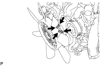
REMOVE DRIVE PLATE AND RING GEAR SUB-ASSEMBLY (for Automatic Transmission)
-
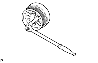
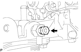
Using a wrench, hold the crankshaft.
Note:Do not turn the crankshaft counterclockwise.
If it is turned counterclockwise, check that the crankshaft pulley set bolt is not loose. If loose, tighten the bolt (Click here).
108 N*m 1101 kgf*cm 80 ft.*lbf or more -
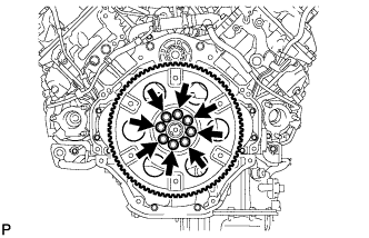
Remove the 8 bolts.
-
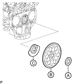
Remove the rear drive plate spacer labeled A, drive plate and ring gear labeled B and rear crankshaft balancer weight labeled C.
-
- Click here
REMOVE FLYWHEEL SUB-ASSEMBLY (for Manual Transmission)
-
Using a wrench, hold the crankshaft.
Note:Do not turn the crankshaft counterclockwise.
If it is turned counterclockwise, check that the crankshaft pulley set bolt is not loose. If loose, tighten the bolt (Click here).
108 N*m 1101 kgf*cm 80 ft.*lbf or more -
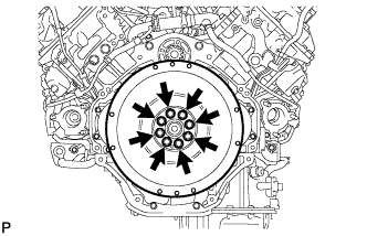
Remove the 8 bolts and flywheel.
-
- Click here
INSTALL ENGINE STAND
-
Install the engine onto an engine stand with bolts.
-
Remove the 4 bolts and No. 1 and No. 2 engine hangers.
-
-
Click here
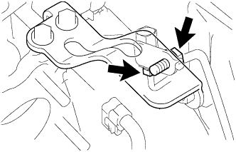
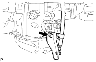
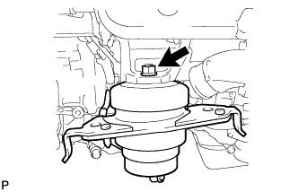
REMOVE FRONT ENGINE MOUNTING INSULATOR RH
-
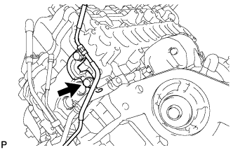
Disconnect the vacuum hose.
-
Remove the nut and mounting insulator.
-
- Click here
REMOVE FRONT ENGINE MOUNTING INSULATOR LH
-
Remove the nut and mounting insulator.
-