REAR CRANKSHAFT OIL SEAL INSTALLATION

-
INSTALL REAR CRANKSHAFT OIL SEAL
-
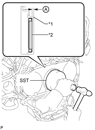
Text in Illustration *1 Rear Engine Oil Seal Retainer *2 Oil Seal Using SST and a hammer, tap in a new oil seal as shown in the illustration.
- SST
- 09223-56010
Standard depth A 2.7 to 3.7 mm (0.106 to 0.147 in.) Note
-
Keep the lip free from foreign matter.
-
Do not tap on the seal at an angle.
-
Make sure that the lip of the oil seal is properly installed.
-
-
INSTALL DRIVE PLATE AND RING GEAR SUB-ASSEMBLY (for Automatic Transmission)
-
Using a wrench, hold the crankshaft.
-
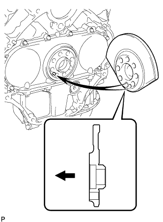
Install the rear crankshaft balancer weight.
Text in Illustration 
Engine Side Tech Tips
-
Align the pin hole of the rear crankshaft balancer weight with the pin of the crankshaft.
-
As the rear crankshaft balancer weight is not reversible, be sure to install it so that it is facing in the direction shown in the illustration.
-
-
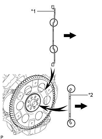
Text in Illustration *1 Drive Plate and Ring Gear *2 Rear Drive Plate Spacer Automatic Transmission Side Install the drive plate and ring gear and rear drive plate spacer with 8 new bolts.
Tech Tips
As the drive plate and ring gear and rear drive plate spacer are not reversible, be sure to install them so that they are facing in the direction shown in the illustration.
-
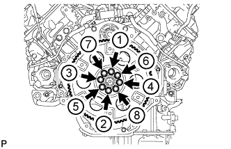
Install and uniformly tighten the 8 bolts in the sequence shown in the illustration.
- Torque:
- 182 N*m { 1856 kgf*cm, 134 ft.*lbf }
-
-
INSTALL FLYWHEEL SUB-ASSEMBLY (for Manual Transmission)
-
Temporarily install the flywheel with 8 new bolts.
Note
-
Align the crankshaft knock pin and flywheel knock pin hole.
-
Do not strike or damage the flywheel installation bolts. Be sure to handle them carefully.
-
Make sure there is no oil on the bolts.
-
-
Using a wrench, hold the crankshaft.
-
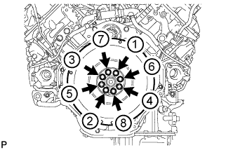
Uniformly install and tighten the 8 bolts in the sequence shown in the illustration.
- Torque:
- 182 N*m { 1856 kgf*cm, 134 ft.*lbf }
-
-
INSTALL CLUTCH DISC ASSEMBLY (for Manual Transmission)
-
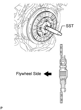
Insert SST into the clutch disc, then insert the clutch disc into the flywheel.
- SST
- 09301-00120
Note
Take care not to insert the clutch disc in the wrong direction.
-
-
INSTALL CLUTCH COVER ASSEMBLY (for Manual Transmission)
-
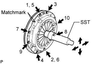
Align the matchmark on the clutch cover with the one on the flywheel.
-
In the order shown in the illustration, temporarily install the 8 bolts starting from the bolt located near the knock pin on the top.
-
Check that the disc is in the center by lightly moving SST up and down, and left and right.
- SST
- 09301-00120
-
Evenly tighten the bolts by following the order shown in the illustration.
- Torque:
- 39 N*m { 400 kgf*cm, 29 ft.*lbf }
-
-
INSTALL AUTOMATIC TRANSMISSION ASSEMBLY
-
INSTALL MANUAL TRANSMISSION UNIT ASSEMBLY
-
CONNECT CABLE TO NEGATIVE BATTERY TERMINAL
Note
When disconnecting the cable, some systems need to be initialized after the cable is reconnected Click here.
-
Connect the cables to the negative (-) main battery and sub-battery terminals.
-