ENGINE UNIT INSTALLATION

-
INSTALL FUEL INJECTOR SEAL (w/ DPF)
-
Install 2 new fuel injector seals.
-
-
INSTALL EXHAUST FUEL ADDITION INJECTOR ASSEMBLY (w/ DPF)
Note
If there is foreign matter on the installation surface of the exhaust fuel addition injector, be sure to clean it before installation.
-
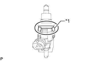
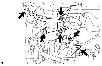
Text in Illustration *1 Nozzle Holder Clamp Install 2 new gaskets, the 2 exhaust fuel addition injectors, 2 nozzle holder clamps and 2 new washers with the 2 bolts.
- Torque:
- 28 N*m { 286 kgf*cm, 21 ft.*lbf }
Tech Tips
Align the nozzle holder clamp with the cutouts of the injector as shown in the illustration.
-
-
INSTALL COMPRESSOR BRACKET
-
Install the compressor bracket with the bolt.
- Torque:
- 21 N*m { 214 kgf*cm, 15 ft.*lbf }
-
-
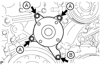
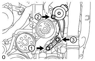
INSTALL V-RIBBED BELT TENSIONER ASSEMBLY
-
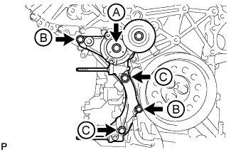
Install the V-ribbed belt tensioner with the 5 bolts.
- Torque:
- for bolt A and C
- 43 N*m { 438 kgf*cm, 32 ft.*lbf }
- for bolt B
- 21 N*m { 214 kgf*cm, 15 ft.*lbf }
Bolt Length Item Quantity Length Bolt A 1 116 mm (4.57 in.) Bolt B 2 40 mm (1.58 in.) Bolt C 2 95 mm (3.74 in.) -
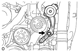
Install the No. 1 idler pulley with the bolt.
- Torque:
- 43 N*m { 438 kgf*cm, 32 ft.*lbf }
-
Install the V-ribbed belt tensioner bracket with the 3 bolts.
- Torque:
- 10 N*m { 102 kgf*cm, 7 ft.*lbf }
-
-
INSTALL STIFFENER INSULATOR RH (w/ Intercooler)
-
Install the stiffener insulator RH with the 2 bolts.
- Torque:
- 10 N*m { 102 kgf*cm, 7 ft.*lbf }
-
-
INSTALL OIL PRESSURE REGULATOR ASSEMBLY
-
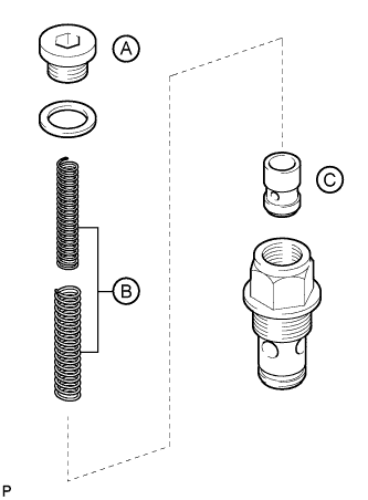
Hold the oil pressure regulator body in a vise between aluminum plates.
-
Apply a light coat of engine oil to the oil pump relief valve labeled C.
-
Install the oil pump relief valve labeled C to the oil pressure regulator body.
-
Install the 2 springs labeled B to the oil pressure regulator body.
-
Using a 10 mm hexagon wrench, install a new gasket and the oil pump relief valve plug labeled A.
- Torque:
- 50 N*m { 510 kgf*cm, 37 ft.*lbf }
-
Apply a light coat of engine oil to a new O-ring, and install it to the oil pressure regulator body.
-
Using a 26 mm wrench, install a new gasket and the oil pressure regulator.
- Torque:
- 86 N*m { 877 kgf*cm, 63 ft.*lbf }
-
-
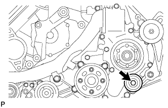
INSTALL OIL FILTER BRACKET DRAIN COCK ASSEMBLY
-
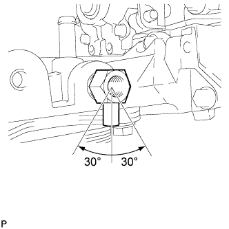
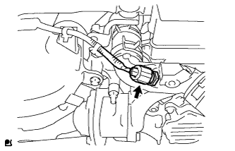
Install the drain cock.
- Torque:
- 20 N*m { 204 kgf*cm, 15 ft.*lbf }
-
Using a 17 mm wrench, rotate the drain cock clockwise (360°) and align the position of the drain hole so that it is within the range shown in the illustration after tightening the drain cock to the specified torque.
Note
-
As the oil filter bracket may be damaged, the maximum tightening torque should be 80 N*m (816 kgf*cm, 59 ft.*lbf) or less.
-
Do not rotate the drain cock more than 1 revolution (360°) after tightening the drain cock with the specified torque.
-
Do not expose the drain cock to coolant within 1 hour after installation.
-
-
Install the oil filter drain cock plug.
- Torque:
- 13 N*m { 130 kgf*cm, 9 ft.*lbf }
-
-
INSTALL OIL TANK BRACKET
-
Install the oil tank bracket with the bolt.
- Torque:
- 10 N*m { 102 kgf*cm, 7 ft.*lbf }
-
-
INSTALL NO. 2 CYLINDER BLOCK INSULATOR
-
INSTALL ENGINE MOUNTING BRACKET LH
-
Install the engine mounting bracket LH with the 4 bolts.
- Torque:
- 80 N*m { 816 kgf*cm, 59 ft.*lbf }
-
-
INSTALL NO. 2 WATER BY-PASS PIPE SUB-ASSEMBLY
-
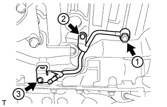
Temporarily install a new gasket and No. 2 water by-pass pipe with the union bolt and 2 bolts.
-
Tighten the union bolt and 2 bolts of the No. 2 water by-pass pipe in the order shown in the illustration.
- Torque:
- for union bolt
- 35 N*m { 357 kgf*cm, 26 ft.*lbf }
- for bolt
- 10 N*m { 102 kgf*cm, 7 ft.*lbf }
-
-
INSTALL NO. 3 VACUUM TRANSMITTING PIPE SUB-ASSEMBLY
-
Install the No. 3 vacuum transmitting pipe with the 2 bolts.
- Torque:
- 6.0 N*m { 61 kgf*cm, 53 in.*lbf }
-
w/ Intercooler:
Connect the vacuum hose.
-
-
INSTALL TURBOCHARGER WIRE
-
Install the turbocharger wire with the 2 bolts.
- Torque:
- 21 N*m { 214 kgf*cm, 15 ft.*lbf }
-
Attach the 3 wire harness clamps.
-
-
INSTALL NO. 2 INTAKE AIR CONNECTOR BRACKET
-
Install the No. 2 intake air connector bracket with the bolt.
- Torque:
- 21 N*m { 214 kgf*cm, 15 ft.*lbf }
-
Attach the 2 wire clamps.
-
-
INSTALL NO. 1 CYLINDER BLOCK INSULATOR
-
INSTALL ENGINE MOUNTING BRACKET RH
-
Install the engine mounting bracket RH with the 4 bolts.
- Torque:
- 80 N*m { 816 kgf*cm, 59 ft.*lbf }
-
-
INSTALL NO. 4 VACUUM TRANSMITTING PIPE SUB-ASSEMBLY (w/ Intercooler)
-
Install the No. 4 vacuum transmitting pipe with the 2 bolts.
- Torque:
- 6.0 N*m { 61 kgf*cm, 53 in.*lbf }
-
Connect the vacuum hose.
-
-
INSTALL NO. 1 WATER BY-PASS PIPE SUB-ASSEMBLY
-
Temporarily install a new gasket and the No. 1 water by-pass pipe with the union bolt and bolt.
-
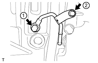
Tighten the union bolt and bolt of the No. 1 water by-pass pipe in the order shown in the illustration.
- Torque:
- for union bolt
- 35 N*m { 357 kgf*cm, 26 ft.*lbf }
- for bolt
- 10 N*m { 102 kgf*cm, 7 ft.*lbf }
-
-
INSTALL AIR TUBE SUPPORT
-
Install the air tube support with the 2 bolts.
- Torque:
- 21 N*m { 214 kgf*cm, 15 ft.*lbf }
-
-
INSTALL NO. 1 INTAKE AIR CONNECTOR BRACKET
-
Install the No. 1 intake air connector bracket with the 2 bolts.
- Torque:
- 21 N*m { 214 kgf*cm, 15 ft.*lbf }
-
-
INSTALL REAR CYLINDER HEAD PLATE LH (w/o EGR System)
-
Install a new gasket and the rear cylinder head plate LH with the 2 bolts.
- Torque:
- 29 N*m { 296 kgf*cm, 21 ft.*lbf }
Tech Tips
The gasket claw should face toward the plate.
-
-
INSTALL REAR CYLINDER HEAD PLATE RH (w/o EGR System)
-
Install a new gasket and the rear cylinder head plate RH with the 2 bolts.
- Torque:
- 29 N*m { 296 kgf*cm, 21 ft.*lbf }
Tech Tips
The gasket claw should face toward the plate.
-
-
INSTALL CYLINDER HEAD COVER SILENCER LH (w/o DPF)
-
w/ Intercooler:
Install the cylinder head cover silencer LH with the 3 bolts.
- Torque:
- 5.0 N*m { 51 kgf*cm, 44 in.*lbf }
-
-
INSTALL CYLINDER HEAD COVER SILENCER RH (w/o DPF)
-
w/ Intercooler:
Install the cylinder head cover silencer RH with the 3 bolts.
- Torque:
- 5.0 N*m { 51 kgf*cm, 44 in.*lbf }
-
-
INSTALL NO. 1 VACUUM TRANSMITTING PIPE SUB-ASSEMBLY (w/o DPF)
-
Install the vacuum transmitting pipe with the 3 bolts.
- Torque:
- 6.0 N*m { 61 kgf*cm, 53 in.*lbf }
-
w/ Intercooler:
Connect the 2 vacuum hoses.
-
-
INSTALL NO. 1 VACUUM SWITCHING VALVE ASSEMBLY (w/o DPF)
-
Install the vacuum switching valve with the bolt.
- Torque:
- 6.0 N*m { 61 kgf*cm, 53 in.*lbf }
-
Connect the 2 vacuum hoses.
-
-
INSTALL FAN BRACKET SUB-ASSEMBLY
-
Install the fan bracket with the 4 bolts.
- Torque:
- 21 N*m { 214 kgf*cm, 15 ft.*lbf }
Bolt Length Item Length Bolt A 30 mm (1.18 in.) Bolt B 80 mm (3.15 in.)
-
-
INSTALL NO. 2 IDLER PULLEY BRACKET (w/ Viscous Heater)
-
Temporarily install the No. 2 idler pulley bracket with the bolt.
-
Temporarily install the 2 bolts to the No. 2 idler pulley bracket bolt hole.
-
Uniformly tighten the 3 bolts of the No. 2 idler pulley bracket in the order shown in the illustration.
- Torque:
- 49 N*m { 495 kgf*cm, 36 ft.*lbf }
-
-
INSTALL NO. 2 IDLER PULLEY (w/ Viscous Heater)
-
Install the collar, No. 2 idler pulley and cover with the bolt.
- Torque:
- 49 N*m { 495 kgf*cm, 36 ft.*lbf }
-
-
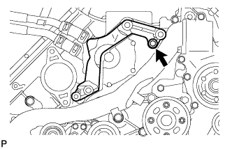
INSTALL NO. 3 ENGINE HANGER
-
Install the No. 3 engine hanger with the 2 bolts.
- Torque:
- 43 N*m { 438 kgf*cm, 32 ft.*lbf }
-
-
INSTALL NO. 1 INTERCOOLER SUPPORT BRACKET
-
Install the No. 1 intercooler support bracket with the 2 bolts.
- Torque:
- 21 N*m { 214 kgf*cm, 15 ft.*lbf }
-
-
INSTALL FUEL PUMP MOTOR WIRE
-
Install the fuel pump wire with the bolt.
- Torque:
- 6.0 N*m { 61 kgf*cm, 53 in.*lbf }
Tech Tips
Attach the claw of the bracket to the timing gear case when installing the bracket.
-
-
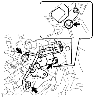
INSTALL GLOW PLUG ASSEMBLY
-
Clean the glow plug and glow plug hole.
-
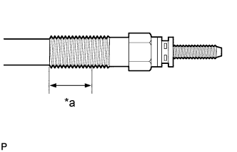
Text in Illustration *a 12 Thread Roots Apply adhesive to 3 or more thread roots in the area shown in the illustration.
Adhesive Toyota Genuine Adhesive 1324, Three Bond 1324 or equivalent -
Using a 10 mm deep socket wrench, install the 8 glow plugs.
- Torque:
- 12 N*m { 125 kgf*cm, 9 ft.*lbf }
-
-
INSTALL NO. 1 GLOW PLUG CONNECTOR
-
Install the 2 glow plug connectors by uniformly tightening the 8 nuts.
- Torque:
- 2.2 N*m { 22 kgf*cm, 19 in.*lbf }
-
Install the 8 screw grommets.
-
Connect the 2 wire harnesses with the 2 nuts and 2 screw grommets.
- Torque:
- 4.0 N*m { 41 kgf*cm, 35 in.*lbf }
-
-
INSTALL CLUTCH FLEXIBLE HOSE BRACKET (for Manual Transmission)
-
Install the clutch flexible hose bracket with the 2 bolts.
- Torque:
- 20 N*m { 204 kgf*cm, 15 ft.*lbf }
-
-
INSTALL NO. 1 AND NO. 2 WATER OUTLET PIPES AND WATER BY-PASS OUTLET
-
Align the painted mark of the No. 1 water hose joint with the protrusion of the water by-pass outlet and connect the water by-pass outlet to the No. 1 water hose joint.
-
Align the painted mark of the No. 1 water hose joint with the painted mark of the No. 2 water outlet pipe and connect the No. 2 water outlet pipe to the No. 1 water hose joint.
-
Connect a new gasket and the No. 1 and No. 2 water outlet pipes with the 2 bolts.
- Torque:
- 21 N*m { 214 kgf*cm, 15 ft.*lbf }
Tech Tips
The gasket claws can face the No. 1 or No. 2 water outlet pipe.
-
-
INSTALL WATER OUTLET PIPE
-
Install 2 new gaskets and the water outlet pipe with the 4 bolts.
- Torque:
- 21 N*m { 214 kgf*cm, 15 ft.*lbf }
Tech Tips
The gasket claw should face toward the water outlet pipe.
-
-
INSTALL WATER OUTLET
-
Install a new gasket and the water outlet with the 2 bolts, and then connect the water outlet to the No. 2 water hose joint.
- Torque:
- 21 N*m { 214 kgf*cm, 15 ft.*lbf }
-
-
INSTALL NO. 2 INTERCOOLER SUPPORT BRACKET
-
Install the No. 2 intercooler support bracket with the 2 bolts.
- Torque:
- 43 N*m { 438 kgf*cm, 32 ft.*lbf }
-
-
INSTALL DIESEL ENGINE COOLANT TEMPERATURE SENSOR
-
Install a new gasket to the sensor.
-
Using a 19 mm deep socket wrench, install the sensor.
- Torque:
- 20 N*m { 204 kgf*cm, 15 ft.*lbf }
-
Connect the sensor connector.
-
-
CONNECT INLET WATER HOSE
-
INSTALL STARTER HOSE BRACKET
-
Install the starter hose bracket with the 2 bolts.
- Torque:
- 10 N*m { 102 kgf*cm, 7 ft.*lbf }
-
-
INSTALL STARTER ASSEMBLY
-
Install the starter with the 2 bolts.
- Torque:
- 80 N*m { 816 kgf*cm, 59 ft.*lbf }
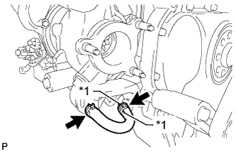
-

Text in Illustration *1 Yellow Mark Connect the 2 starter hoses.
-
Attach the harness clamp and connect the wire harness.
-
Connect the starter wire with the nut.
- Torque:
- 20 N*m { 200 kgf*cm, 14 ft.*lbf }
-
Connect the starter connector.
-
-
INSTALL TIMING GEAR COVER INSULATOR (w/ Intercooler)
-
w/o Viscous Heater:
Install the timing gear cover insulator with the 2 bolts.
- Torque:
- 21 N*m { 214 kgf*cm, 15 ft.*lbf }
-
w/ Viscous Heater:
Install the timing gear cover insulator.
-
-
INSTALL THERMOSTAT
-
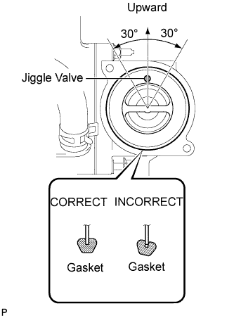
Install a new gasket to the thermostat.
Note
When installing the gasket to the thermostat, be careful not to deform the gasket. Make sure that the groove of the gasket is properly installed onto the thermostat, as shown in the illustration.
-
Insert the thermostat into the water pump with the jiggle valve facing straight upward.
Tech Tips
The jiggle valve may be set within 30° of either side of the prescribed position.
-
-
INSTALL WATER INLET
-
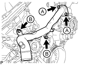
Install the water inlet with the 4 bolts.
- Torque:
- for bolt A
- 21 N*m { 214 kgf*cm, 15 ft.*lbf }
- for bolt B
- 25 N*m { 250 kgf*cm, 18 ft.*lbf }
-
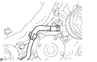
Connect the No. 2 oil cooler hose to the clamp and water pump.
-
-
INSTALL NO. 1 IDLER PULLEY BRACKET (w/ Viscous Heater)
-
Install the No. 1 idler pulley bracket with the bolt.
- Torque:
- 49 N*m { 495 kgf*cm, 36 ft.*lbf }
-
-
INSTALL VISCOUS HEATER ASSEMBLY WITH MAGNET CLUTCH (w/ Viscous Heater)
-
Install the heater assembly with the 2 bolts.
- Torque:
- 48.5 N*m { 495 kgf*cm, 36 ft.*lbf }
-
Connect the 2 heater hoses.
-
Using pliers, grip the claws of the clips and slide the 2 clips.
-
Connect the connector and attach the clamp.
-
-
INSTALL NO. 2 TURBOCHARGER SUB-ASSEMBLY WITH EXHAUST MANIFOLD LH
-
Install a new gasket to the No. 2 turbocharger.
-
Install the exhaust manifold LH to the No. 2 turbocharger with 3 new nuts.
- Torque:
- 69 N*m { 704 kgf*cm, 51 ft.*lbf }
Tech Tips
The gasket claw should face toward the outside of the vehicle.
-
w/ DPF:
-
Install 2 new gaskets to the No. 2 exhaust manifold pipe.
Tech Tips
The gasket claws should face the No. 2 exhaust manifold pipe.
-
Temporarily install the No. 2 exhaust manifold pipe with the 4 bolts.
Tech Tips
Install the No. 2 exhaust manifold pipe so that it is oriented as shown in the illustration.
-
Tighten the 4 bolts.
- Torque:
- 21 N*m { 214 kgf*cm, 15 ft.*lbf }
-
-
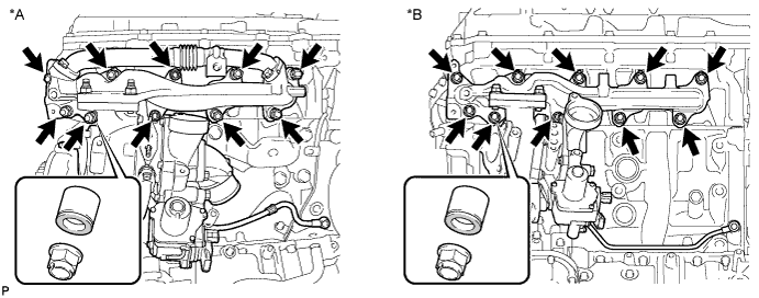
Install a new gasket to the cylinder head LH.
-
Install the No. 2 turbocharger with exhaust manifold LH and 10 collars to the cylinder head LH with 10 new nuts.
- Torque:
- 36 N*m { 367 kgf*cm, 27 ft.*lbf }
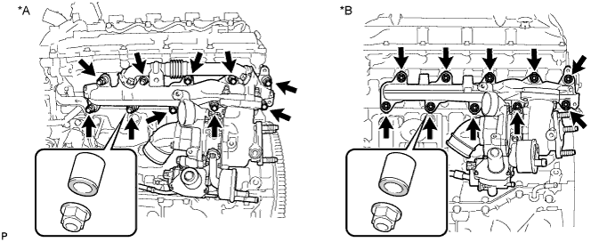
Text in Illustration *A w/ DPF *B w/o DPF Tech Tips
Install the collars with the colored side facing the nuts.
-
Install a new gasket and the No. 2 inlet turbo oil pipe to the No. 1 oil pan with the union bolt.
- Torque:
- 29 N*m { 296 kgf*cm, 21 ft.*lbf }
-
Connect the 2 connectors to the turbocharger.
-
-
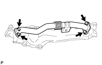
INSTALL NO. 2 VENTILATION TUBE SUB-ASSEMBLY
-
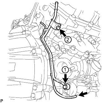
Temporarily install a new gasket and the No. 2 ventilation tube with the union bolt and bolt.
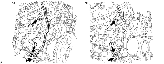
Text in Illustration *A w/ DPF *B w/o DPF -
Tighten the union bolt and bolt in the order shown in the illustration.
- Torque:
- for union bolt
- 29 N*m { 296 kgf*cm, 21 ft.*lbf }
- for bolt
- 10 N*m { 102 kgf*cm, 7 ft.*lbf }
Note
Clean and remove any oil in the area labeled 1 in the illustration.
-
Connect the hose.
-
-
INSTALL NO. 2 TURBOCHARGER STAY
-
Install the No. 2 turbocharger stay with the 2 bolts.
- Torque:
- 49 N*m { 495 kgf*cm, 36 ft.*lbf }
-
-
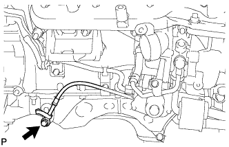
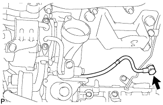
CONNECT NO. 2 OUTLET TURBO OIL HOSE
Tech Tips
Align the white paint marks on the oil hose and pipe, and connect the hose.
Text in Illustration *1 Painted Mark -
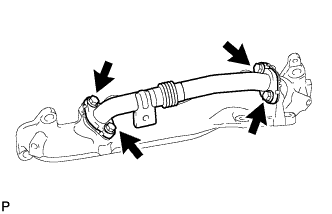
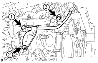
INSTALL NO. 2 TURBO WATER PIPE SUB-ASSEMBLY
-
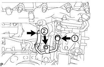
Temporarily install a new gasket and the No. 2 turbo water pipe with the union bolt and bolt.
-
Tighten the union bolt and bolt in the order shown in the illustration.
- Torque:
- for union bolt
- 35 N*m { 357 kgf*cm, 26 ft.*lbf }
- for bolt
- 10 N*m { 102 kgf*cm, 7 ft.*lbf }
-
Connect the water hose to the pipe.
-
-
INSTALL FRONT WATER BY-PASS JOINT
-
Install a new gasket and the front water by-pass joint.
- Torque:
- 50 N*m { 510 kgf*cm, 37 ft.*lbf }
-
-
INSTALL NO. 3 TURBO WATER PIPE SUB-ASSEMBLY
-
Temporarily install a new gasket and the No. 3 turbo water pipe with the union bolt and 2 bolts.
-
Tighten the union bolt and 2 bolts in the order shown in the illustration.
- Torque:
- for union bolt
- 35 N*m { 357 kgf*cm, 26 ft.*lbf }
- for bolt
- 10 N*m { 102 kgf*cm, 7 ft.*lbf }
-
-
INSTALL NO. 2 EXHAUST MANIFOLD HEAT INSULATOR
-
Install the No. 2 exhaust manifold heat insulator with the 3 bolts.
- Torque:
- 25 N*m { 255 kgf*cm, 18 ft.*lbf }
-
-
INSTALL NO. 2 TURBO WATER HOSE
-
INSTALL BREATHER PLUG LH
-
Install the breather plug LH.
-
w/o DPF:
Attach the clamp.
-
Connect the hose.
-
-
INSTALL NO. 3 VENTILATION HOSE
-
INSTALL NO. 1 TURBOCHARGER SUB-ASSEMBLY WITH EXHAUST MANIFOLD RH
-
Install a new gasket to the No. 1 turbocharger.
-
Install the exhaust manifold RH to the No. 1 turbocharger with 2 new nuts and the bolt.
- Torque:
- 69 N*m { 704 kgf*cm, 51 ft.*lbf }
-
w/ DPF:
-
Install 2 new gaskets to the No. 1 exhaust manifold pipe.
Tech Tips
The gasket claws should face the No. 1 exhaust manifold pipe.
-
Temporarily install the No. 1 exhaust manifold pipe with the 4 bolts.
Tech Tips
Install the No. 1 exhaust manifold pipe so that it is oriented as shown in the illustration.
-
Tighten the 4 bolts.
- Torque:
- 21 N*m { 214 kgf*cm, 15 ft.*lbf }
-
-
Install a new gasket to the cylinder head RH.
-
Install the No. 1 turbocharger with exhaust manifold RH to the cylinder head RH with the 10 collars and 10 new nuts.
- Torque:
- 36 N*m { 367 kgf*cm, 27 ft.*lbf }
Text in Illustration *A w/ DPF *B w/o DPF Tech Tips
Install the collars with the colored side facing the nuts.
-
Install a new gasket and the No. 1 inlet turbo oil pipe to the cylinder block with the union bolt.
- Torque:
- When "dry"
- 29 N*m { 296 kgf*cm, 21 ft.*lbf }
- When "wet"
- 23 N*m { 235 kgf*cm, 17 ft.*lbf }
Note
-
The parts are "dry" when there is absolutely no engine oil on the union bolt and cylinder block bolt hole.
-
The parts are "wet" when there is engine oil on the union bolt and cylinder block bolt hole.
-
-
INSTALL NO. 1 VENTILATION TUBE SUB-ASSEMBLY
-
Temporarily install a new gasket and the No. 1 ventilation tube with the union bolt and bolt.
-
Tighten the union bolt and bolt in the order shown in the illustration.
- Torque:
- for union bolt
- 29 N*m { 296 kgf*cm, 21 ft.*lbf }
- for bolt
- 10 N*m { 102 kgf*cm, 7 in.*lbf }
Note
Clean and remove any oil in the area labeled 1 in the illustration.
-
Connect the hose.
-
-
INSTALL NO. 1 TURBOCHARGER STAY
-
Temporarily install the No. 1 turbocharger stay with the 2 bolts.
-
Tighten the 2 bolts.
- Torque:
- 49 N*m { 495 kgf*cm, 36 ft.*lbf }
-
-
INSTALL NO. 1 TURBO WATER PIPE SUB-ASSEMBLY
-
Text in Illustration *1 New Nut Install a new gasket and the No. 1 turbo water pipe with 2 new nuts and the 3 bolts.
- Torque:
- 10 N*m { 102 kgf*cm, 7 ft.*lbf }
-
Connect the water hose.
-
-
CONNECT NO. 1 OUTLET TURBO OIL HOSE
-
INSTALL NO. 1 EXHAUST MANIFOLD HEAT INSULATOR
-
Install the No. 1 exhaust manifold heat insulator with the 3 bolts.
- Torque:
- 25 N*m { 255 kgf*cm, 18 ft.*lbf }
-
-
INSTALL NO. 2 TURBO WATER HOSE
-
INSTALL BREATHER PLUG RH
-
Install the breather plug RH and attach the clamp.
-
Connect the hose.
-
-
INSTALL NO. 2 VENTILATION HOSE
-
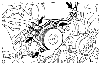
INSTALL GENERATOR ASSEMBLY
-
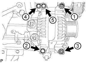
Temporarily install the generator with the 3 bolts and 2 nuts.
-
Uniformly tighten the 3 bolts and 2 nuts in the order shown in the illustration.
- Torque:
- 21 N*m { 214 kgf*cm, 15 ft.*lbf }
-
Connect the generator cable and install the nut and bolt.
- Torque:
- for bolt
- 13 N*m { 133 kgf*cm, 10 ft.*lbf }
- for nut (130A Type and 150A Type:)
- 9.8 N*m { 100 kgf*cm, 87 in.*lbf }
- for nut (180A Type:)
- 12 N*m { 122 kgf*cm, 9 ft.*lbf }
-
-
INSTALL NO. 1 INTAKE AIR CONNECTOR PIPE
-
Install the No. 1 intake air connector pipe with the bolt. Then tighten the hose clamp.
- Torque:
- for bolt
- 21 N*m { 214 kgf*cm, 15 ft.*lbf }
- for hose clamp
- 6.0 N*m { 61 kgf*cm, 53 in.*lbf }
-
Connect the 4 connectors and attach the 5 wire harness clamps.
-
-
INSTALL NO. 1 ENGINE OIL LEVEL DIPSTICK GUIDE
-
Apply a light coat of engine oil to a new O-ring and install it to the No. 1 engine oil level dipstick guide.
-
Install the No. 1 engine oil level dipstick guide with the 2 bolts.
- Torque:
- 10 N*m { 102 kgf*cm, 7 ft.*lbf }
-
-
INSTALL VACUUM PUMP ASSEMBLY (w/ Intercooler)
-
Apply engine oil to 2 new O-rings.
-
Install the 2 O-rings to the vacuum pump.
-
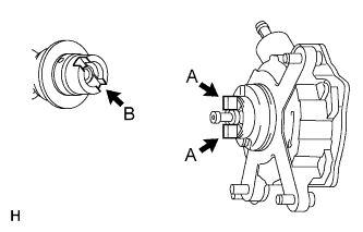
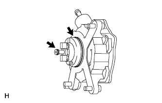
Install the vacuum pump so that the coupling teeth of the vacuum pump (labeled A) and the groove of the camshaft (labeled B) are aligned.
Note
Be careful not to damage the O-ring.
-
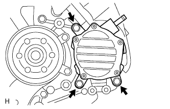
Install the vacuum pump with the 3 bolts.
- Torque:
- 21 N*m { 214 kgf*cm, 15 ft.*lbf }
Note
Confirm that the vacuum pump is not at an angle, and that there is no clearance between the fitting surfaces.
-