ENGINE UNIT DISASSEMBLY

CAUTION:
When replacing an injector (including interchanging injectors between cylinders), common rail, cylinder head, or intake manifold, replace the corresponding injection pipes with a new one.
-
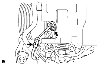
REMOVE CAMSHAFT POSITION SENSOR

-
Disconnect the sensor connector.
-
Remove the bolt and sensor.
-
-
REMOVE CRANKSHAFT POSITION SENSOR
-
Disconnect the sensor wire harness clamp.
-
Remove the bolt and sensor.
-
-
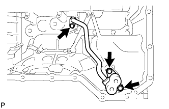
DISCONNECT NO. 1 OIL COOLER HOSE
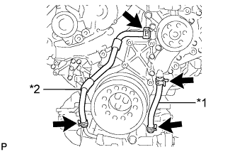
Text in Illustration *1 No. 1 Oil Cooler Hose *2 No. 2 Oil Cooler Hose -
DISCONNECT NO. 2 OIL COOLER HOSE
-
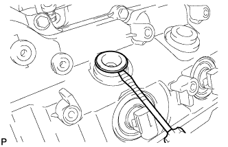
REMOVE CRANKSHAFT PULLEY
Note

This procedure is intended for removal/installation of the crankshaft pulley only. Do not use this procedure for removal/installation of the flywheel or the drive plate and ring gear.
Text in Illustration *1 Service Hole *2 Protrusion
-
Install the 2 bolts to the bolt holes of the crankshaft rear side.
-
Using a bar, turn the crankshaft until the crankshaft pulley service hole is a little to the left of bottom dead center.
-
Install a 14 mm x 1.5 pitch service bolt with a length of 70 mm or more to the crankshaft pulley service hole, and hold the crankshaft using the timing chain cover protrusion.
-
Remove the 3 bolts and crankshaft pulley.
Note
If the crankshaft pulley cannot be removed, temporarily install a bolt to the crankshaft so that the pulley does not fall, and lightly tap the outer edge of the mass damper with a plastic-faced hammer to remove the pulley. Do not tap the pulley V-ribbed belt ribs, as the crankshaft may be damaged.
-
-
REMOVE TIMING GEAR COVER SPACER (w/ Intercooler)
-
Remove the 2 bolts and timing gear cover spacer.
-
-
REMOVE OIL FILTER CAP WITH ELEMENT
-

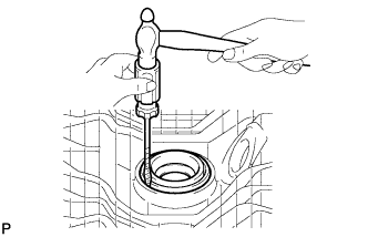
Remove the oil filter drain plug.
-
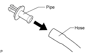
Connect a hose with an inside diameter of 15 mm (0.591 in.) to the pipe.
-
Remove the O-ring from the oil filter drain plug and install it to the drain pipe.
-

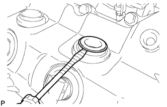
Install the oil filter drain pipe to the oil filter cap and drain the engine oil.
-
Remove the oil filter drain pipe.
-
Apply a light coat of engine oil to a new O-ring, and install it to the oil filter drain plug.
-
Install the oil filter drain plug to the oil filter cap.
- Torque:
- 13 N*m { 127 kgf*cm, 9 ft.*lbf }
-
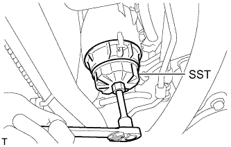
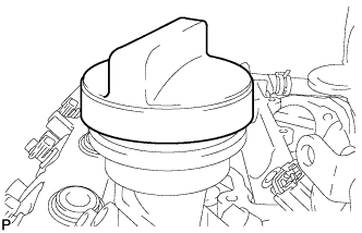
Using SST, remove the oil filter cap.
- SST
- 09228-06501
Tech Tips
Use a container to catch the draining oil. After the oil filter cap is loosened approximately 4 turns and the cap ribs are vertical, engine oil drains from the gap between the oil filter cap and oil pan.
-

Remove the oil filter element and O-ring from the oil filter cap.
Note
Be sure to remove the cap O-ring by hand, without using any tools, to prevent damage to the cap O-ring groove.
-
-
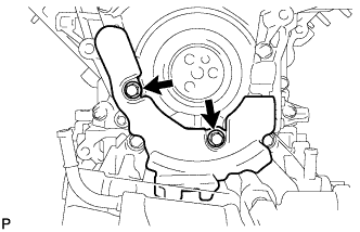
REMOVE OIL PRESSURE SENDER GAUGE ASSEMBLY
-

Disconnect the oil pressure sender gauge connector.
-
Remove the oil pressure sender gauge.
-
-
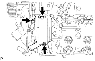
REMOVE OIL COOLER ASSEMBLY
-

Remove the 2 bolts, 2 nuts and oil cooler.
-
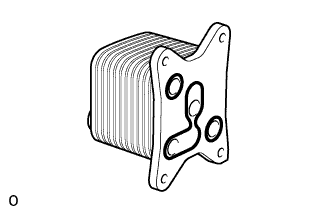
Remove the 2 O-rings and oil cooler gasket.
-
-
REMOVE OIL COOLER RELIEF VALVE ASSEMBLY
-

Remove the oil cooler relief valve and gasket.
-
-
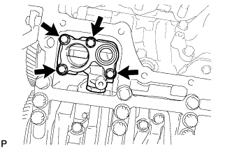
REMOVE OIL FILTER BRACKET SUB-ASSEMBLY
-
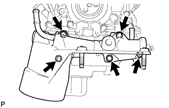
Remove the 3 bolts, 2 nuts and oil filter bracket.
-
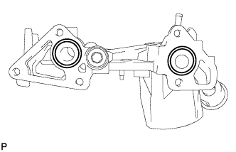
Remove the 2 O-rings.
-
-
REMOVE ENGINE OIL LEVEL SENSOR
-
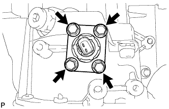
Remove the 4 bolts and engine oil level sensor.
-
Remove the gasket.
-
-
REMOVE OIL PAN DRAIN PLUG
-
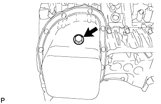
Remove the oil pan drain plug and gasket.
-
-
REMOVE NO. 2 OIL PAN SUB-ASSEMBLY
-
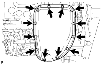
Remove the 10 bolts and 2 nuts.
-

Insert the blade of an oil pan seal cutter between the oil pans. Cut through the applied sealer and remove the No. 2 oil pan.
Note
Be careful not to damage the contact surfaces of the No. 1 and No. 2 oil pans.
-
-
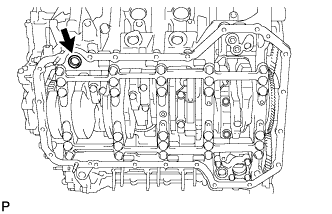
REMOVE OIL STRAINER SUB-ASSEMBLY
-
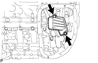
Remove the 2 bolts and oil strainer.
-
Remove the O-ring from the oil strainer.
-
-
REMOVE NO. 1 OIL PAN SUB-ASSEMBLY
-
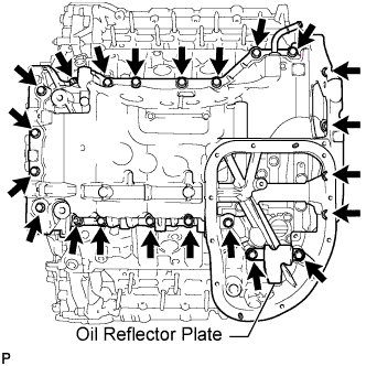
Remove the 20 bolts, 2 nuts and oil reflector plate.
Note
If the oil reflector plate is deformed, replace it.
Tech Tips
Be sure to clean the bolts and stud bolts, and check the threads for cracks or other damage.
-
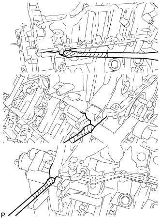
Remove the No. 1 oil pan by prying between the No. 1 oil pan and cylinder block with a screwdriver.
Note
Be careful not to damage the contact surfaces of the cylinder block and oil pan.
Tech Tips
Tape the screwdriver tip before use.
-

Remove the 3 O-rings.
-
Remove the cylinder block oil hole gasket.
-
-
REMOVE NO. 1 OIL PAN BAFFLE PLATE
-
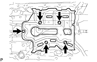
Remove the 5 bolts and No. 1 oil pan baffle plate.
-
-
REMOVE INLET OIL PUMP PIPE
-
Remove the 3 bolts and inlet oil pump pipe.
-
Remove the O-ring from the inlet oil pump pipe.
-
-
REMOVE OIL REGULATOR ASSEMBLY
-
Remove the 4 bolts and oil regulator.
-
-
REMOVE REAR ENGINE OIL SEAL RETAINER
-
Remove the 10 bolts.
-
Remove the oil seal retainer by prying between the oil seal retainer and cylinder block with a screwdriver.
Tech Tips
Tape the screwdriver tip before use.
-
-
REMOVE REAR CRANKSHAFT OIL SEAL
-

Place the oil seal retainer on wooden blocks.
-
Using a screwdriver and hammer, tap out the oil seal.
Tech Tips
Tape the screwdriver tip before use.
-
-
REMOVE OIL PUMP ASSEMBLY
-
Remove the 4 bolts and oil pump.
-
-
REMOVE SCAVENGING PUMP ASSEMBLY
-
Remove the 4 bolts and scavenging pump.
-
-
REMOVE OIL FILLER CAP SUB-ASSEMBLY
-
REMOVE OIL FILLER CAP GASKET
-
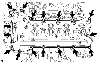
REMOVE CYLINDER HEAD COVER SUB-ASSEMBLY RH (w/o DPF)
-

Remove the 18 bolts, cylinder head cover and gasket.
-
-
REMOVE NOZZLE HOLDER GASKET RH (w/o DPF)
-
Using a small screwdriver and hammer, remove the 4 nozzle holder gaskets.
Tech Tips
Tape the screwdriver tip before use.
-
-
REMOVE NOZZLE HOLDER SEAL RH (w/o DPF)
-
Using a small screwdriver, remove the 4 holder seals by prying the portion between each holder seal and the cutout part of the cylinder head cover.
Tech Tips
Tape the screwdriver tip before use.
-
-
REMOVE CYLINDER HEAD COVER INSULATOR RH (w/ DPF)
-
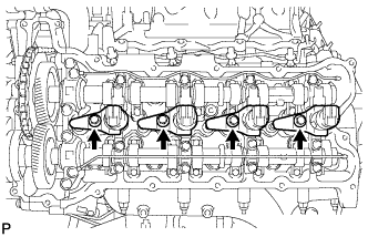
REMOVE FUEL INJECTOR RH (w/ DPF)
-
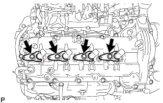
Remove the 4 bolts, 4 washers, 4 nozzle holder clamps and 4 injectors.
Tech Tips
Arrange the injectors, holder clamps, washers and bolts in the correct order.
-
Remove the O-ring from each injector.
-
Remove the 4 injection nozzle seats from the cylinder head.
-
-
REMOVE CYLINDER HEAD COVER SUB-ASSEMBLY RH (w/ DPF)
-
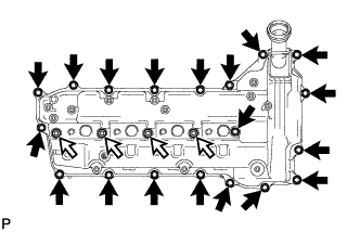
Remove the 19 bolts, 4 nozzle holder clamp seats and cylinder head cover RH.
Text in Illustration 
Bolt 
Nozzle Holder Clamp Seat -
Remove the cylinder head cover gasket RH and No. 3 cylinder head cover gasket from the cylinder head cover RH.
-
-
REMOVE NO. 2 FUEL PUMP BRACKET (w/ DPF)
-
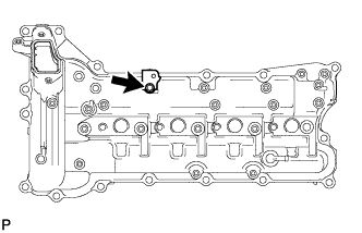
Remove the bolt and No. 2 fuel pump bracket.
-
-
REMOVE CYLINDER HEAD COVER INSULATOR LH (w/ DPF)
-
REMOVE FUEL INJECTOR LH (w/ DPF)
-
Remove the 4 bolts, 4 washers, 4 nozzle holder clamps and 4 injectors.
Tech Tips
Arrange the injectors, holder clamps, washers and bolts in the correct order.
-
Remove the O-ring from each injector.
-
Remove the 4 injection nozzle seats from the cylinder head.
-
-
REMOVE OIL SEPARATOR ASSEMBLY
-
Remove the 3 bolts, oil separator and gasket.
-
-
REMOVE CYLINDER HEAD COVER SUB-ASSEMBLY LH (w/ DPF)
-

Remove the 18 bolts, 4 nozzle holder clamp seats and cylinder head cover LH.
Text in Illustration Bolt Nozzle Holder Clamp Seat -
Remove the cylinder head cover gasket LH and No. 4 cylinder head cover gasket from the cylinder head cover LH.
-
-
REMOVE CYLINDER HEAD COVER SUB-ASSEMBLY LH (w/o DPF)
-
Remove the 17 bolts, cylinder head cover and gasket.
-
-
REMOVE NOZZLE HOLDER GASKET LH (w/o DPF)
-
Using a small screwdriver and hammer, remove the 4 nozzle holder gaskets.
Tech Tips
Tape the screwdriver tip before use.
-
-
REMOVE NOZZLE HOLDER SEAL LH (w/o DPF)
-
Using a small screwdriver, remove the 4 holder seals by prying the portion between each holder seal and the cutout part of the cylinder head cover.
Tech Tips
Tape the screwdriver tip before use.
-
-
REMOVE FUEL INJECTOR RH (w/o DPF)
-
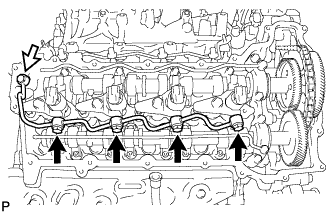
Remove the union bolt, 4 hollow screws, 5 gaskets and nozzle leakage pipe.
Text in Illustration Union Bolt Note
-
When removing the nozzle leakage pipe, place a cushion under the pipe.
-
Be careful not to deform or scratch the union seal surface.
-
After removing the nozzle leakage pipe, put it in a plastic bag to prevent foreign matter from contaminating its injector inlet.
-
-

Remove the 4 bolts, 4 washers, 4 nozzle holder clamps and 4 injectors.
Tech Tips
Arrange the injectors, holder clamps, washers and bolts in the correct order.
-
Remove the O-ring from each injector.
-
Remove the 4 injection nozzle seats from the cylinder head.
-
-
REMOVE FUEL INJECTOR LH (w/o DPF)
-

Remove the union bolt, 4 hollow screws, 5 gaskets and No. 2 nozzle leakage pipe.
Text in Illustration Union Bolt Note
-
When removing the nozzle leakage pipe, place a cushion under the pipe.
-
Be careful not to deform or scratch the union seal surface.
-
After removing the nozzle leakage pipe, put it in a plastic bag to prevent foreign matter from contaminating its injector inlet.
-
-
Remove the 4 bolts, 4 washers, 4 nozzle holder clamps and 4 injectors.
Tech Tips
Arrange the injectors, holder clamps, washers and bolts in the correct order.
-
Remove the O-ring from each injector.
-
Remove the 4 injection nozzle seats from the cylinder head.
-
-
REMOVE WATER PUMP ASSEMBLY
-
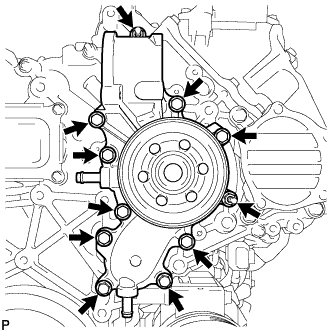
Remove the 9 bolts, 2 nuts, water pump and gasket.
-
-
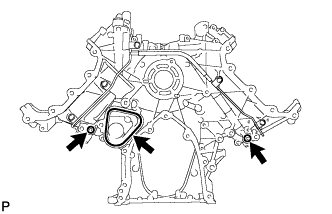
REMOVE TIMING CHAIN COVER PLATE
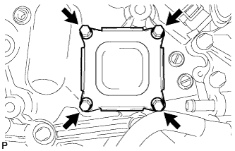
-
Remove the 4 bolts, cover plate and gasket.
-
-
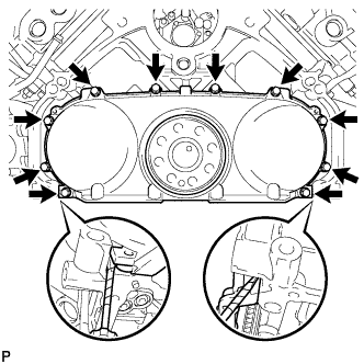
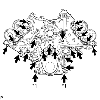
REMOVE TIMING CHAIN COVER SUB-ASSEMBLY
-
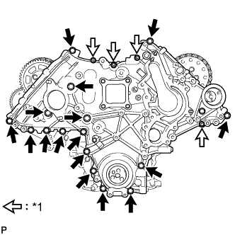
Text in Illustration *1 Nut Remove the 4 nuts and 16 bolts.
-
Using a screwdriver, remove the timing chain cover by prying between the timing chain cover and timing gear case.
Tech Tips
Tape the screwdriver tip before use.
-
Remove the O-ring from the timing gear case.
-
-
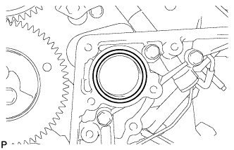
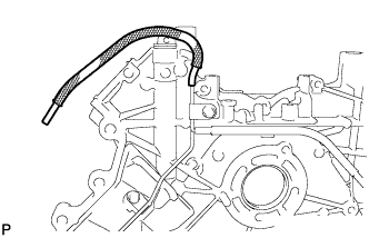
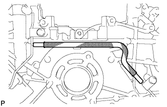
REMOVE FRONT CRANKSHAFT OIL SEAL
-

Text in Illustration *1 Wooden Block Place the timing chain cover on wooden blocks.
-
Using a screwdriver and wooden block, pry out the oil seal.
Note
Do not damage the surface of the oil seal press fit hole.
Tech Tips
Tape the screwdriver tip before use.
-
-
SET NO. 1 CYLINDER TO TDC/COMPRESSION
-
Temporarily install the 2 crankshaft pulley set bolts to the crankshaft.
-
Turn the crankshaft clockwise to set the No. 1 cylinder to TDC.
-
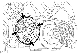
With the crankshaft key 45° counterclockwise from the top position, check that the timing marks of the RH and LH camshaft timing gears are aligned. If not as specified, turn the crankshaft 1 revolution (360°) and align the timing marks as shown below.
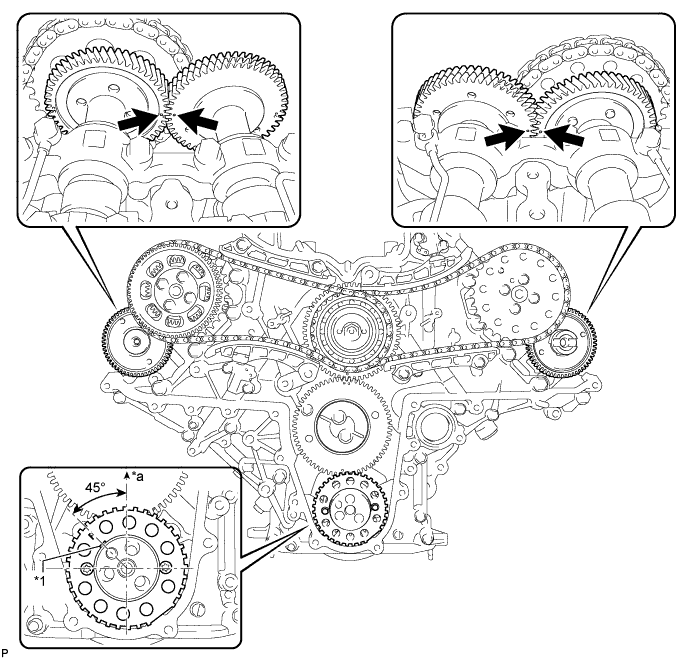
Text in Illustration *1 Key - - *a Top - - -
Remove the 2 crankshaft pulley set bolts.
-
-
REMOVE NO. 1 CRANKSHAFT POSITION SENSOR PLATE
-
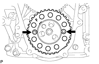
Using a T30 "TORX" wrench, remove the 2 screws and crankshaft position sensor plate.
-
-
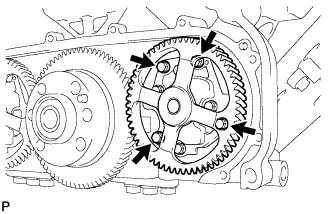
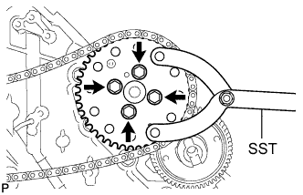
REMOVE PUMP DRIVE SHAFT GEAR
-

Using SST, hold the pump drive shaft gear.
- SST
- 09960-10010 ( 09962-01000, 09963-01000 )
-
Remove the 4 bolts and pump drive shaft gear.
-
-
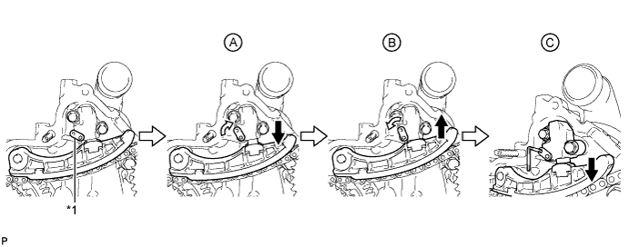
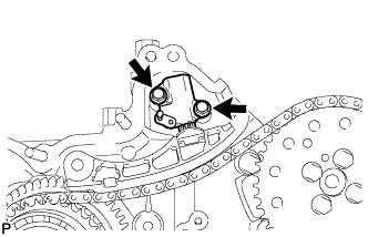
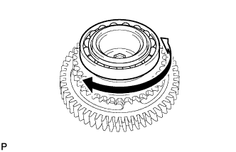
REMOVE NO. 1 CHAIN TENSIONER ASSEMBLY
-
Push the tensioner slipper away from the tensioner, and move the stopper plate clockwise to release the lock as shown in A.
-
Push down the tensioner slipper and move the stopper plate counterclockwise to set the lock as shown in B.
-
Push the tensioner slipper away from the tensioner, and insert a hexagon wrench into the stopper plate hole as shown in C.

Text in Illustration *1 Stopper Plate - - -

Remove the 2 bolts and No. 1 chain tensioner.
-
-
REMOVE NO. 1 CHAIN TENSIONER SLIPPER
-
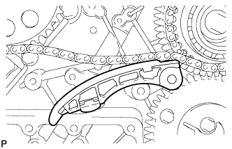
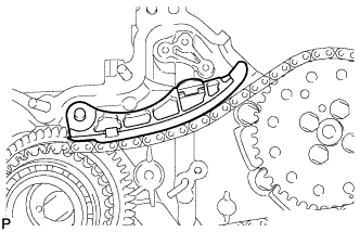
REMOVE NO. 1 CHAIN VIBRATION DAMPER
-
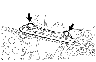
Remove the 2 bolts and No. 1 chain vibration damper.
-
-
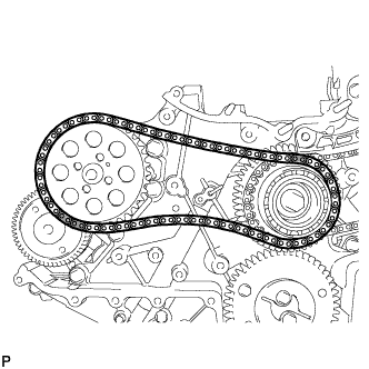
REMOVE NO. 1 CAMSHAFT TIMING SPROCKET AND NO. 1 TIMING CHAIN
-
REMOVE NO. 2 CHAIN TENSIONER ASSEMBLY
-
Push the tensioner slipper away from the tensioner, and move the stopper plate clockwise to release the lock as shown in A.
-
Push up the tensioner slipper and move the stopper plate counterclockwise to set the lock as shown in B.
-
Push the tensioner slipper away from the tensioner, and insert a hexagon wrench into the stopper plate hole as shown in C.
Text in Illustration *1 Stopper Plate - - -
Remove the 2 bolts and No. 2 chain tensioner.
-
-
REMOVE NO. 2 CHAIN TENSIONER SLIPPER
-
REMOVE NO. 2 CHAIN VIBRATION DAMPER
-
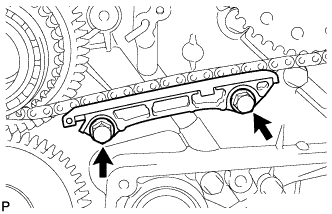
Remove the 2 bolts and No. 2 chain vibration damper.
-
-
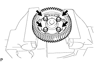
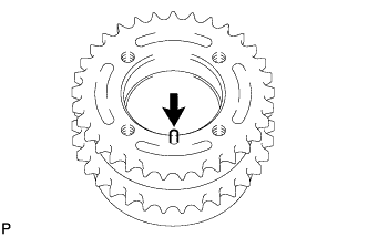
REMOVE NO. 2 CAMSHAFT TIMING SPROCKET AND NO. 2 TIMING CHAIN
-
Using SST, hold the No. 2 camshaft timing sprocket.
- SST
- 09960-10010 ( 09962-01000, 09963-01000 )
-
Remove the 4 bolts, No. 2 camshaft timing sprocket and No. 2 timing chain.
-
-
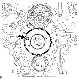
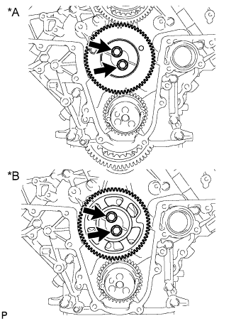
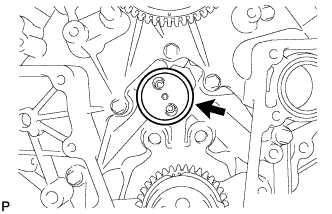
REMOVE FUEL SUPPLY PUMP DRIVE GEAR NUT
-
Using SST, hold the idle gear.
- SST
- 09960-10010 ( 09962-01000, 09963-00700 )
-
Remove the nut.

Text in Illustration *A w/ Intercooler *B w/o Intercooler
-
-
REMOVE IDLE GEAR ASSEMBLY
-
w/ Intercooler:
Using an 8 mm x 1.25 pitch service bolt with a length of 15 mm or more, fix the idle gear in place.
- Torque:
- 13 N*m { 133 kgf*cm, 10 ft.*lbf }
-
Text in Illustration *A w/ Intercooler *B w/o Intercooler Remove the 2 bolts, idle gear thrust plate and idle gear.
-
-
SEPARATE SUB IDLE GEAR, IDLE GEAR SPRING AND IDLE GEAR (w/ Intercooler)
-
Hold the idle gear in a vise between aluminum plates.
Note
Be careful not to damage the gears.
-
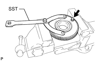
Using SST, hole the idle gear, and remove the bolt and sub idle gear.
- SST
- 09960-10010 ( 09962-01000, 09963-00700 )
-
Remove the idle gear spring from the idle gear.
-
-
REMOVE NO. 1 IDLE GEAR SHAFT
-
REMOVE FUEL SUPPLY PUMP DRIVE GEAR
-
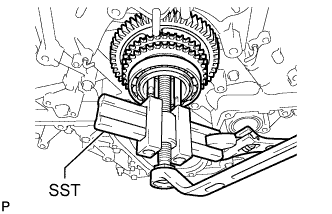
Using SST, remove the fuel supply pump drive gear.
- SST
- 09950-50013 ( 09951-05010, 09952-05010, 09953-05020, 09954-05031 )
-
-
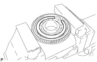
INSPECT RADIAL BALL BEARING
-
Turn the bearing, and check that the bearing moves smoothly and quietly.
If it moves roughly or noisily, replace the radial ball bearing.
-
-
REMOVE RADIAL BALL BEARING

Tech Tips
It is not necessary to remove the bearing unless it is being replaced.
-
Using SST, remove the radial ball bearing.
- SST
- 09950-00020
- 09950-00030
- 09950-60010 ( 09951-00580 )
- 09950-40011 ( 09957-04010 )
-
-
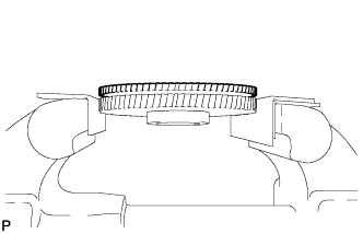
SEPARATE FUEL SUPPLY PUMP DRIVE GEAR AND FUEL SUPPLY PUMP SHAFT SPROCKET
-
Hold the fuel supply pump shaft sprocket in a vise between aluminum plates.
Note
Be careful not to damage the gears.
-
Remove the 4 bolts and separate the fuel supply pump drive gear and fuel supply pump shaft sprocket.
-
-
REMOVE STRAIGHT PIN
Tech Tips
It is not necessary to remove the straight pin unless it is being replaced.
-
Remove the straight pin.
-
-
REMOVE FUEL SUPPLY PUMP ASSEMBLY
-
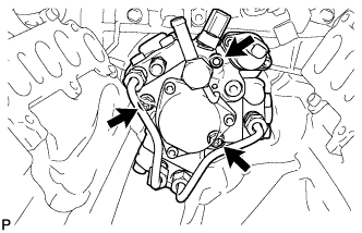
Using a 6 mm hexagon wrench, remove the hexagon bolt. Then remove the 2 nuts and fuel supply pump.
-
Remove the O-ring.
-
-
REMOVE V-BANK SILENCER
-
REMOVE TIMING GEAR CASE SUB-ASSEMBLY
-
Text in Illustration *1 Nut Remove the 22 bolts, 2 nuts and timing gear case shown in the illustration.
-
Remove the 2 O-rings and timing gear case gasket.
-
-
DISCONNECT NO. 2 VACUUM TRANSMITTING HOSE (w/ Intercooler)
-
DISCONNECT NO. 3 VACUUM TRANSMITTING HOSE (w/ Intercooler)
-
REMOVE NO. 1 VACUUM TRANSMITTING PIPE SUB-ASSEMBLY (w/ Intercooler)
-
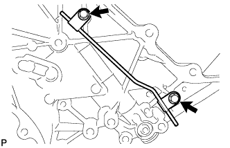
Remove the 2 bolts and No. 1 vacuum transmitting pipe.
-
-
REMOVE NO. 2 VACUUM TRANSMITTING PIPE SUB-ASSEMBLY (w/ Intercooler)
-
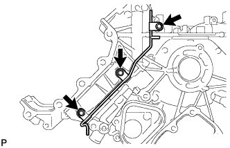
Remove the 3 bolts and No. 2 vacuum transmitting pipe.
-
-
REMOVE NO. 2 TIMING GEAR CASE INSULATOR (w/ Intercooler)
-
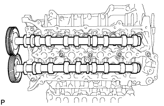
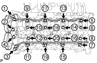
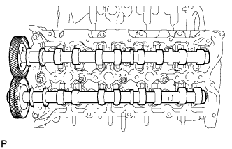
REMOVE NO. 1 AND NO. 2 CAMSHAFTS
-
Using a 6 mm x 1.0 pitch service bolt with a length of 16 mm or more, fix the No. 1 camshaft in place.
- Torque:
- 8.0 N*m { 82 kgf*cm, 71 in.*lbf }
-
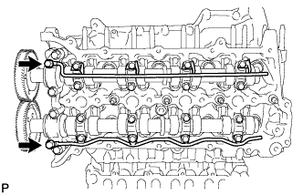
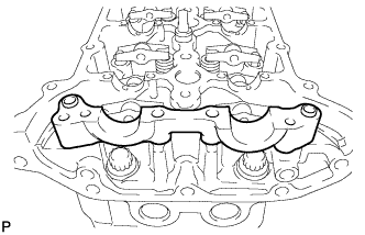
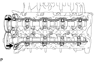
Loosen the 2 union bolts.
-
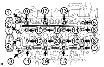
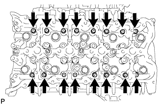
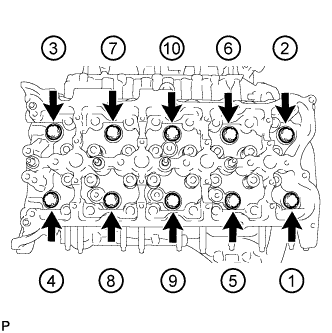
Uniformly loosen and remove the 20 bolts in the sequence shown in the illustration.
-
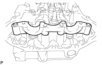
Remove the 2 union bolts and No. 1 and No. 2 oil feed pipes.
-
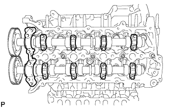
Remove the 8 No. 3 camshaft bearing caps and No. 1 camshaft bearing cap.
Tech Tips
Be sure to arrange the removed parts for each installation position separately.
-
Remove the No. 1 and No. 2 camshafts.
-
-
REMOVE NO. 2 CAMSHAFT BEARING CAP
-
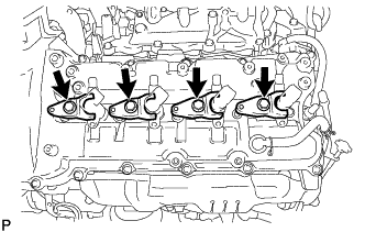
REMOVE NO. 1 VALVE ROCKER ARM
-
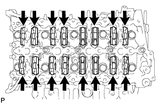
Remove the 16 No. 1 valve rocker arms.
Tech Tips
Be sure to arrange the removed parts for each installation position separately.
-
-
REMOVE NO. 1 VALVE LASH ADJUSTER ASSEMBLY
-
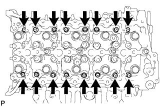
Remove the 16 No. 1 valve lash adjusters.
Tech Tips
Be sure to arrange the removed parts for each installation position separately.
-
-
REMOVE CYLINDER HEAD SUB-ASSEMBLY RH
-
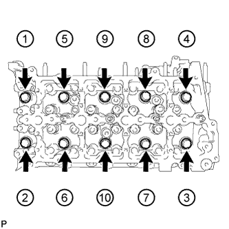
Uniformly loosen and remove the 10 bolts and 10 spacers in the sequence shown in the illustration. Then remove the cylinder head.
Note
-
Be careful not to drop washers into the cylinder head.
-
Head warpage or cracking could result from removing bolts in an incorrect order.
Tech Tips
Be sure to arrange the removed parts for each installation position separately.
-
-
-
REMOVE NO. 1 CYLINDER HEAD GASKET
-
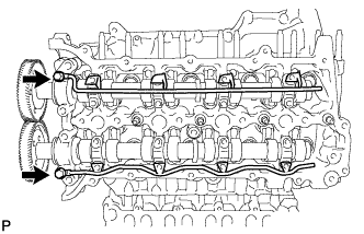
REMOVE NO. 3 AND NO. 4 CAMSHAFTS
-
Using a 6 mm x 1.0 pitch service bolt with a length of 16 mm or more, fix the No. 4 camshaft in place.
- Torque:
- 8.0 N*m { 82 kgf*cm, 71 in.*lbf }
-
Loosen the 2 union bolts.
-
Uniformly loosen and remove the 20 bolts in the sequence shown in the illustration.
-
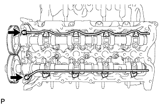
Remove the 2 union bolts and No. 3 and No. 4 oil feed pipes.
-

Remove the 8 No. 3 camshaft bearing caps and No. 4 camshaft bearing cap.
Tech Tips
Be sure to arrange the removed parts for each installation position separately.
-
Remove the No. 3 and No. 4 camshafts.
-
-
REMOVE NO. 5 CAMSHAFT BEARING CAP
-
REMOVE NO. 2 VALVE ROCKER ARM
-

Remove the 16 No. 2 valve rocker arms.
Tech Tips
Be sure to arrange the removed parts for each installation position separately.
-
-
REMOVE NO. 2 VALVE LASH ADJUSTER ASSEMBLY
-
Remove the 16 No. 2 valve lash adjusters.
Tech Tips
Be sure to arrange the removed parts for each installation position separately.
-
-
REMOVE CYLINDER HEAD SUB-ASSEMBLY LH
-
Uniformly loosen and remove the 10 bolts and 10 spacers in the sequence shown in the illustration. Then remove the cylinder head.
Note
-
Be careful not to drop washers into the cylinder head.
-
Head warpage or cracking could result from removing bolts in an incorrect order.
Tech Tips
Be sure to arrange the removed parts for each installation position separately.
-
-
-
REMOVE NO. 2 CYLINDER HEAD GASKET
-
REPLACE STUD BOLT
Tech Tips
If the stud bolt is deformed or the threads are damaged, replace it.
-
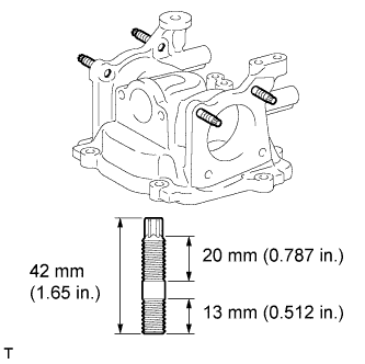
Intake Pipe:
-
Using an E8 "TORX" wrench, replace the 4 stud bolts.
- Torque:
- 6.0 N*m { 61 kgf*cm, 53 in.*lbf }
-
-
No. 3 Intake Manifold:
-
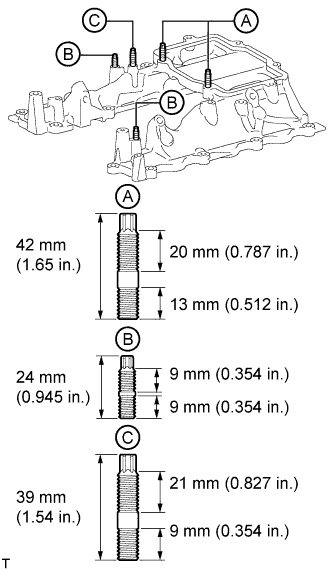
Using an E8 "TORX" wrench, replace the 2 stud bolts labeled A.
- Torque:
- 6.0 N*m { 61 kgf*cm, 53 in.*lbf }
-
Using an E6 "TORX" wrench, replace the 2 stud bolts labeled B.
- Torque:
- 5.0 N*m { 51 kgf*cm, 44 in.*lbf }
-
Using an E6 "TORX" wrench, replace the stud bolt labeled C.
- Torque:
- 4.0 N*m { 41 kgf*cm, 35 in.*lbf }
-
-
Oil Filter Bracket:
-
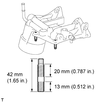
Using an E8 "TORX" wrench, replace the 2 stud bolts.
- Torque:
- 6.0 N*m { 61 kgf*cm, 53 in.*lbf }
-
-
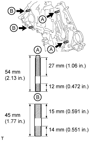
No. 1 Oil Pan:
-

Using an E8 "TORX" wrench, replace the 2 stud bolts labeled A.
- Torque:
- 6.0 N*m { 61 kgf*cm, 53 in.*lbf }
-
Using an E7 "TORX" wrench, replace the 2 stud bolts labeled B.
- Torque:
- 5.2 N*m { 53 kgf*cm, 46 in.*lbf }
-
-
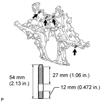
Timing Chain Cover:
-
Using an E7 "TORX" wrench, replace the 2 stud bolts labeled A.
- Torque:
- 6.0 N*m { 61 kgf*cm, 53 in.*lbf }
-
Replace the 2 stud bolts labeled B.
- Torque:
- 12 N*m { 120 kgf*cm, 9 ft.*lbf }
-
-
Timing Gear Case:
-
Using an E7 "TORX" wrench, replace the 4 stud bolts.
- Torque:
- 6.0 N*m { 61 kgf*cm, 53 in.*lbf }
-
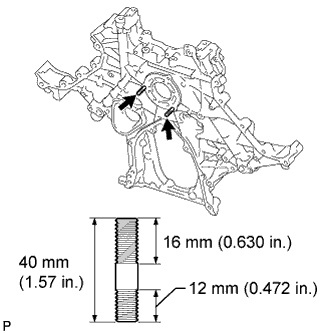
Remove the 2 stud bolts.
-
Remove the adhesive from the threads of the timing gear case.
-
Apply adhesive to 2 or more threads of the 2 stud bolts.
-
Install the 2 stud bolts.
- Torque:
- 10 N*m { 102 kgf*cm, 7 ft.*lbf }
-
-
-
REPLACE STRAIGHT SCREW PLUG
Tech Tips

If water or oil leaks from the straight screw plug or the plug is corroded, replace it.
-
No. 1 Oil Pan:
-
Using a 10 mm hexagon wrench, replace the straight screw plug and/or gasket.
- Torque:
- 50 N*m { 510 kgf*cm, 37 ft.*lbf }
-
Using a 14 mm hexagon wrench, replace the straight screw plug and/or gasket.
- Torque:
- 86 N*m { 877 kgf*cm, 63 ft.*lbf }
-
-
Oil Filter Bracket:
-
Using a 10 mm hexagon wrench, replace the straight screw plug and/or gasket.
- Torque:
- 50 N*m { 510 kgf*cm, 37 ft.*lbf }
-
-
Timing Gear Case:
-

Using a 10 mm hexagon wrench, replace the straight screw plug and/or gasket.
- Torque:
- 40 N*m { 408 kgf*cm, 30 ft.*lbf }
-
-
-
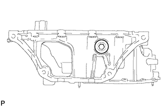
REPLACE CYLINDER BLOCK STRAIGHT SCREW PLUG
Tech Tips
If water leaks from the straight screw plug or the plug is corroded, replace it.
-
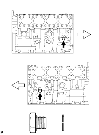
Replace the 2 straight screw plugs and 2 gaskets.
- Torque:
- 38 N*m { 387 kgf*cm, 28 ft.*lbf }
Text in Illustration Front
-
-
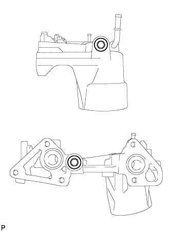
REPLACE RING PIN
Tech Tips
It is not necessary to remove the ring pin unless it is being replaced.
-
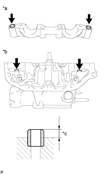
No. 1 and No. 2 Intake Manifold:
-
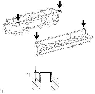
Text in Illustration *a 4.4 to 5.6 mm Replace the ring pin.
Standard protrusion 4.4 to 5.6 mm (0.173 to 0.222 in.)
-
-
Cylinder Head:
-
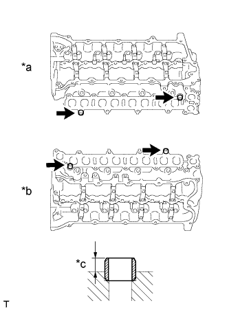
Text in Illustration *a RH *b LH *c 4.4 to 5.6 mm Replace the ring pin.
Standard protrusion 4.4 to 5.6 mm (0.173 to 0.222 in.)
-
-
V-ribbed Belt Tensioner:
-

Text in Illustration *a 4.7 to 5.7 mm Replace the ring pin.
Standard protrusion 4.7 to 5.7 mm (0.185 to 0.224 in.)
-
-
Timing Chain Case:
-
Text in Illustration *a 4.7 to 5.7 mm Replace the ring pin.
Standard protrusion 4.7 to 5.7 mm (0.185 to 0.224 in.)
-
-
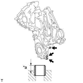
Timing Gear Case:
-

Text in Illustration *a 5.2 to 5.7 mm Replace the ring pin.
Standard protrusion 5.2 to 5.7 mm (0.205 to 0.224 in.)
-
-
Cylinder Head RH:
-

Text in Illustration *a No. 2 Camshaft Bearing Cap *b Cylinder Head RH *c 2.5 to 3.5 mm Replace the ring pin.
Standard protrusion 2.5 to 3.5 mm (0.0984 to 0.138 in.)
-
-
Cylinder Head LH:
-
Text in Illustration *a No. 5 Camshaft Bearing Cap *b Cylinder Head LH *c 2.5 to 3.5 mm Replace the ring pin.
Standard protrusion 2.5 to 3.5 mm (0.0984 to 0.138 in.)
-
-
-
REPLACE CHAIN TENSIONER STRAIGHT PIN
Tech Tips
It is not necessary to remove the straight pin unless it is being replaced.
-

Text in Illustration *a 18 to 20 mm Replace the straight pin.
Standard protrusion 18 to 20 mm (0.709 to 0.787 in.)
-
-
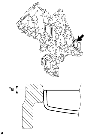
REPLACE TIMING GEAR COVER SET STRAIGHT PIN
Tech Tips
It is not necessary to remove the straight pin unless it is being replaced.
-
Text in Illustration *a 5.0 to 7.5 mm Replace the straight pin.
Standard protrusion 5.0 to 7.5 mm (0.197 to 0.295 in.)
-
-
REPLACE HOLE PLUG (w/o Intercooler)
Tech Tips
It is not necessary to remove a hole plug unless it is being replaced.
-
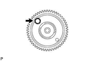
Remove the hole plug from the No. 4 camshaft.
-
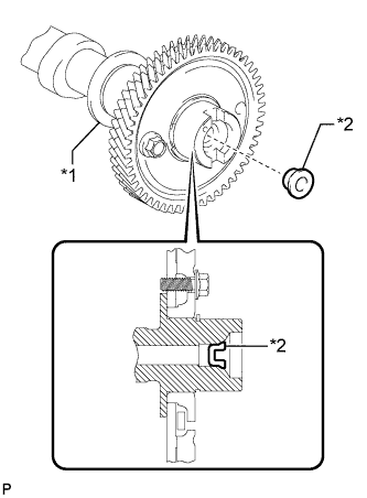
Text in Illustration *1 No. 4 Camshaft *2 Hole Plug Using a 12 mm steel bar and hammer, tap in the hole plug as shown in the illustration.
-
-
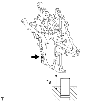
REPLACE TIGHT PLUG (w/o Intercooler)
Note
If oil leaks from a tight plug or a plug is corroded, replace it.
-
Remove the tight plug from the timing chain cover.
-
Apply adhesive to a new tight plug.
Adhesive Toyota Genuine Adhesive 1324, Three Bond 1324 or equivalent -
Text in Illustration *a 0.2 to 0.5 mm Using SST and a hammer, tap in the tight plug as shown in the illustration.
- SST
- 09950-60010 ( 09951-00550 )
- 09950-70010 ( 09951-07100 )
Standard depth 0.2 to 0.5 mm (0.00787 to 0.0197 in.)
-